2D Viewer - Save Grid Image
Save the grid image from the 2D Viewer as PNG, HTML, or PDF file.
To open this panel, select the Save Individual Image option from the Export option ![]() in the 2D Viewer Panel.
in the 2D Viewer Panel.
- Using
- Features
- Additional Resources
Save Grid Image Panel Features
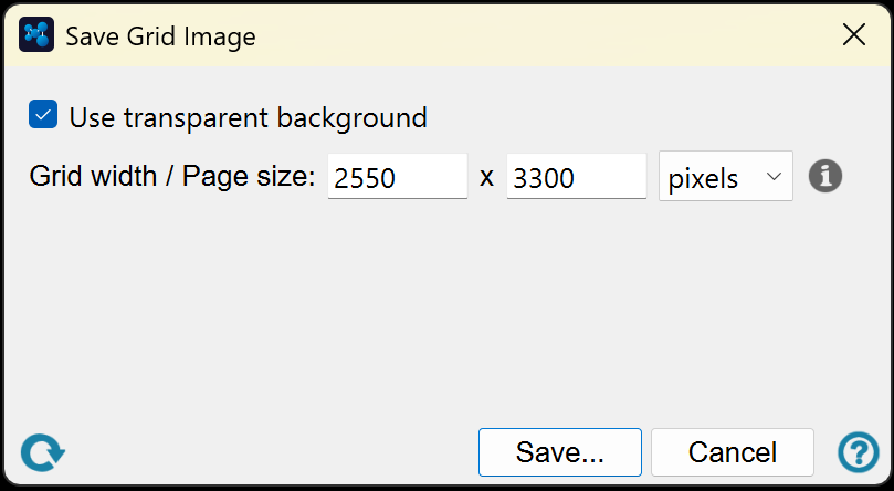
- Use transparent background option (PNG only)
- Canvas Size dialog box
- Save and Cancel buttons
- Reset button
- Use transparent background option (PNG only)
-
Choose whether to have a transparent background or a white background (default) for the image.
- Canvas Size dialog box
-
Enter the size of the canvas for the saved image in inches (default is 4.00) or pixels (default is 1200). The height will be ignored for all formats except PDF. With PDF, the width and height values define the page size.
- Save and Cancel buttons
-
Save Image or Cancel. In PDF format, the images are in the same grid layout as in the panel, with page breaks. In HTML format, the images are presented in a table in the same layout as in the grid. A file selector opens, in which you can choose the format and name the file.
- Change view menu
-
Change the display of the structures. The items on this menu are grouped by function and are listed below. A check mark is displayed next to items that turn on a feature to indicate that the feature is selected.
-
Grid Layout—Display all the structures in a grid of tiles. In the grid layout, you can rearrange the tiles by dragging them to a new location. This is purely for display: it has no effect on the order of the entries in the Project Table.
-
Single Structure—Display one structure at a time. When you choose this item, arrow buttons are shown above the display area, so you can step through the structures. You can also use the left and right arrow keys to step through the structures.
-
Columns—Choose the number of columns in the grid view from this submenu. This item is only available if you choose Grid Layout.
-
Link 2D Selection and Inclusion—When you select one or more structures in the 2D Viewer, automatically include these structures in the Workspace.
-
Display Entry Properties—Display selected entry properties in a list below the structure in each tile.
-
Manage Entry Properties—Select the entry properties that are displayed in each tile. Opens the 2D Viewer - Select Properties Dialog Box, where you can filter and select entry properties for display.
-
Highlight Aligned Substructures—Highlight the maximum common substructure (MCS) between the structure and the reference by coloring the bonds pink. For the reference, the MCS is a combinination of the MCS with all other structures.
-
Display Atom Annotation—Display the selected atom-level property for each atom instead of the atomic symbol. The property is displayed at the position of the atom and is displayed for all atoms, including carbon, and hydrogen if the Show all hydrogens preference is selected.
-
Choose Atom Property—Choose the atom-level property for the display of atom annotation. Opens a dialog box in which you can choose an atom-level property.
-
Show Neutral Form—Show the 2D structure in its neutral form, if it is ionic.
-
2D Structure Preferences—Set preferences for 2D structures. Opens the Preferences Panel at the 2D Structure Preferences.
-
- Display area
-
The structures are displayed in this area, in tiles arranged in a grid. If you choose Change view → Single Structure, only one tile is displayed.
The circle at the top left of a tile can be used to include the structure in the Workspace. This is equivalent to the button in the In column of the Project Table or Entry List. Inclusion of structures in the Workspace is synchronized between this panel and the Project Table and the Entry List: a change in one place changes the other two places. You can include multiple tiles with the usual shift-click and control-click actions.
Properties are displayed in a list below the structure, in a two-column layout with the name on the left and the value on the right. As the space is limited, the text may be truncated, but the full property information is displayed in a tooltip in the format name: value.
In grid layout, the tiles can be moved to a new location by dragging. This allows you to rearrange them as you want; it has no effect on the order of the entries in the Project Table.
You can select tiles with the usual shift-click and control-click actions. With a single tile selected, you can move the selection with the arrow buttons or with the N and P keys on the keyboard or the arrow keys. This is useful when you have Link 2D Selection and Inclusion selected, as the included entry changes as you move the selection. The selection of tiles is independent of the entry selection in the Project Table.
The display area has a shortcut menu for actions on the selected tiles, which is displayed on right-click. Right-clicking selects the tile if it is not already selected. The shortcut menu is grouped by function:
- Workspace inclusion
-
These items control the inclusion and exclusion of structures from the Workspace based on the inclusion status of the structure in the tile you right-clicked. The action is taken on the selected structures. The inclusion items are only present if the clicked tile is not in the Workspace; the exclusion items are present if the tile is in the Workspace.
- Include in 3D Workspace—add the structures to the Workspace, without changing the inclusion of other structures. Equivalent to control-clicking the inclusion buttons.
- Exclude from 3D Workspace—remove the structures from the Workspace, without changing the inclusion of other structures. Equivalent to control-clicking the inclusion buttons.
- Exclude Other Entries—remove all other structures from the Workspace, keeping these structure in the Workspace. Equivalent to including just these structures.
- Project Table selection
-
These items control the selection and deselection of structures in the Project Table based on whether the structure in the tile you right-clicked is selected or not. The action is taken on the entries for the selected tiles. The inclusion items are only present if the entry for the tile clicked is not selected in the Project Table; the exclusion items are present if the entry for the tile is selected in the Project Table.
- Select in Maestro Project—add the entries to the Project Table selection, without changing the selection of other entries.
- Deselect in Maestro Project—remove these entries from the Project Table selection, without changing the selection of other entries.
- Deselect Other Entries—remove all other entries from the Project Table selection, leaving these entries selected.
- Tile actions
-
These items perform actions on either the tile you right-clicked or the selected tiles.
- Copy This Image—copy the 2D image to the clipboard for the tile you right-clicked.
- Set Structure as Reference—make the structure in the tile you right-clicked the reference structure. The 2D image of the reference structure is updated to match the orientation of the 3D structure in the Workspace, and is highlighted in light blue. If structures were aligned to a previous reference, the 2D image reverts to the default and is no longer highlighted.
- Reset to Default Orientation—reset the orientation of the selected structures to their original orientation. Any alignment highlighting is removed.
- Remove from 2D Viewer—remove the selected tiles from the 2D Viewer. This action is only available if Auto-update is not selected.
- Reset button

-
Reset the panel to its default settings, clearing all data.
- Use transparent background option (PNG only)
-
Choose whether to have a transparent background or a white background (default) for the image.
- Canvas Size dialog box
-
Enter the size of the canvas for the saved image in inches (default is 4.00) or pixels (default is 1200). The height will be ignored for all formats except PDF. With PDF, the width and height values define the page size.
- Save and Cancel buttons
-
Save Image or Cancel. In PDF format, the images are in the same grid layout as in the panel, with page breaks. In HTML format, the images are presented in a table in the same layout as in the grid. A file selector opens, in which you can choose the format and name the file.
- Change view menu
-
Change the display of the structures. The items on this menu are grouped by function and are listed below. A check mark is displayed next to items that turn on a feature to indicate that the feature is selected.
-
Grid Layout—Display all the structures in a grid of tiles. In the grid layout, you can rearrange the tiles by dragging them to a new location. This is purely for display: it has no effect on the order of the entries in the Project Table.
-
Single Structure—Display one structure at a time. When you choose this item, arrow buttons are shown above the display area, so you can step through the structures. You can also use the left and right arrow keys to step through the structures.
-
Columns—Choose the number of columns in the grid view from this submenu. This item is only available if you choose Grid Layout.
-
Link 2D Selection and Inclusion—When you select one or more structures in the 2D Viewer, automatically include these structures in the Workspace.
-
Display Entry Properties—Display selected entry properties in a list below the structure in each tile.
-
Manage Entry Properties—Select the entry properties that are displayed in each tile. Opens the 2D Viewer - Select Properties Dialog Box, where you can filter and select entry properties for display.
-
Highlight Aligned Substructures—Highlight the maximum common substructure (MCS) between the structure and the reference by coloring the bonds pink. For the reference, the MCS is a combinination of the MCS with all other structures.
-
Display Atom Annotation—Display the selected atom-level property for each atom instead of the atomic symbol. The property is displayed at the position of the atom and is displayed for all atoms, including carbon, and hydrogen if the Show all hydrogens preference is selected.
-
Choose Atom Property—Choose the atom-level property for the display of atom annotation. Opens a dialog box in which you can choose an atom-level property.
-
Show Neutral Form—Show the 2D structure in its neutral form, if it is ionic.
-
2D Structure Preferences—Set preferences for 2D structures. Opens the Preferences Panel at the 2D Structure Preferences.
-
- Display area
-
The structures are displayed in this area, in tiles arranged in a grid. If you choose Change view → Single Structure, only one tile is displayed.
The circle at the top left of a tile can be used to include the structure in the Workspace. This is equivalent to the button in the In column of the Project Table or Entry List. Inclusion of structures in the Workspace is synchronized between this panel and the Project Table and the Entry List: a change in one place changes the other two places. You can include multiple tiles with the usual shift-click and control-click actions.
Properties are displayed in a list below the structure, in a two-column layout with the name on the left and the value on the right. As the space is limited, the text may be truncated, but the full property information is displayed in a tooltip in the format name: value.
In grid layout, the tiles can be moved to a new location by dragging. This allows you to rearrange them as you want; it has no effect on the order of the entries in the Project Table.
You can select tiles with the usual shift-click and control-click actions. With a single tile selected, you can move the selection with the arrow buttons or with the N and P keys on the keyboard or the arrow keys. This is useful when you have Link 2D Selection and Inclusion selected, as the included entry changes as you move the selection. The selection of tiles is independent of the entry selection in the Project Table.
The display area has a shortcut menu for actions on the selected tiles, which is displayed on right-click. Right-clicking selects the tile if it is not already selected. The shortcut menu is grouped by function:
- Workspace inclusion
-
These items control the inclusion and exclusion of structures from the Workspace based on the inclusion status of the structure in the tile you right-clicked. The action is taken on the selected structures. The inclusion items are only present if the clicked tile is not in the Workspace; the exclusion items are present if the tile is in the Workspace.
- Include in 3D Workspace—add the structures to the Workspace, without changing the inclusion of other structures. Equivalent to control-clicking the inclusion buttons.
- Exclude from 3D Workspace—remove the structures from the Workspace, without changing the inclusion of other structures. Equivalent to control-clicking the inclusion buttons.
- Exclude Other Entries—remove all other structures from the Workspace, keeping these structure in the Workspace. Equivalent to including just these structures.
- Project Table selection
-
These items control the selection and deselection of structures in the Project Table based on whether the structure in the tile you right-clicked is selected or not. The action is taken on the entries for the selected tiles. The inclusion items are only present if the entry for the tile clicked is not selected in the Project Table; the exclusion items are present if the entry for the tile is selected in the Project Table.
- Select in Maestro Project—add the entries to the Project Table selection, without changing the selection of other entries.
- Deselect in Maestro Project—remove these entries from the Project Table selection, without changing the selection of other entries.
- Deselect Other Entries—remove all other entries from the Project Table selection, leaving these entries selected.
- Tile actions
-
These items perform actions on either the tile you right-clicked or the selected tiles.
- Copy This Image—copy the 2D image to the clipboard for the tile you right-clicked.
- Set Structure as Reference—make the structure in the tile you right-clicked the reference structure. The 2D image of the reference structure is updated to match the orientation of the 3D structure in the Workspace, and is highlighted in light blue. If structures were aligned to a previous reference, the 2D image reverts to the default and is no longer highlighted.
- Reset to Default Orientation—reset the orientation of the selected structures to their original orientation. Any alignment highlighting is removed.
- Remove from 2D Viewer—remove the selected tiles from the 2D Viewer. This action is only available if Auto-update is not selected.
- Reset button
-
Reset the panel to its default settings, clearing all data.