Best Practices for Protein Preparation
PPW, best practices, protein best practices, protein prep
Proper protein preparation is critical to the success of any modeling efforts. This document describes what are considered to be the best practices for preparing proteins.
Best Practices for Protein Preparation
Before preparing your protein
Understanding the Nature of Your Protein
Understanding what kind of protein you have is important for the preparation task.
Membrane-bound proteins — Knowing and orienting the transmembrane region of your system can be critical to subsequent modeling steps. The OPM database contains a range of structures pre-aligned so that the transmembrane region is perfectly oriented for other Schrödinger tools such as the Desmond System Builder (Fig. 1). If you’re going to use tools such as Desmond in subsequent modeling steps it could be worthwhile obtaining your structure from the OPM database. If your structure isn’t in the OPM, it might still be worthwhile hunting out a close analog to assist you with alignment.
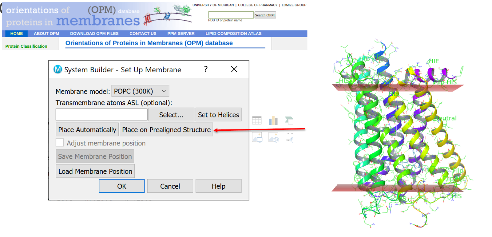
Figure 1. Using the OPM pre-aligned structure for use in Desmond’s System Builder
Metalloproteins — What is the nature of the metal? What are their oxidation states? What coordination shells are usual for this ion? You might need this information when selecting the charge state for the metal ions in subsequent stages.
Enzyme structural forms — Does your protein exist in various states, such as kinases and proteases? For example, a kinase might be active, inactive, DFG-in, or DFG-out (Fig. 2). Ensure you have the right form to avoid wasting time on preparation.
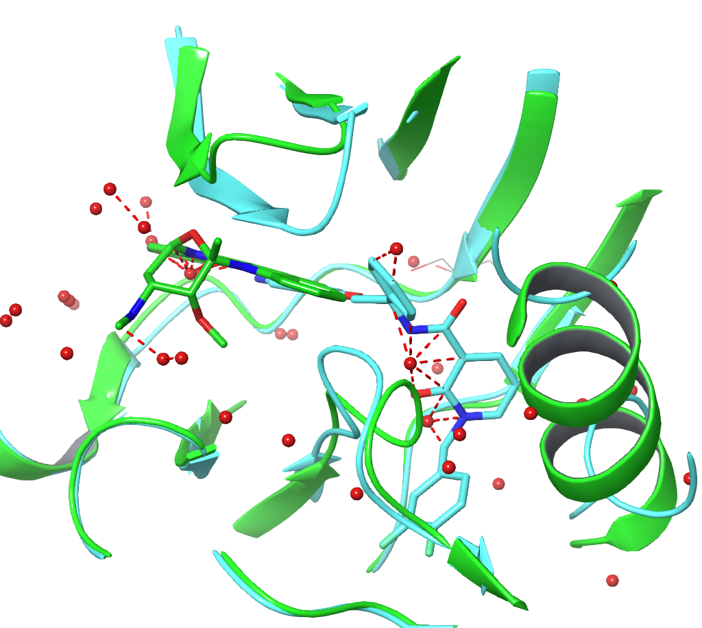
Figure 2. Alignment of 3QC4 and 1OKY showing differences in the DFG-In (10KY) and DFG-Out (3QC4) tertiary structure close to the binding site region
Enzyme chemical forms — Similarly, does your protein need certain residues to take on an unusual protonation/tautomerization state as part of its mechanism of action? Do you want to model a catalytically active form of the enzyme or its resting state? Fig 3. shows the typical catalytic cycle of a serine protease, together with a structure of plasma-kallikrein, showing the proximity of the critical histidine to the bound inhibitor.
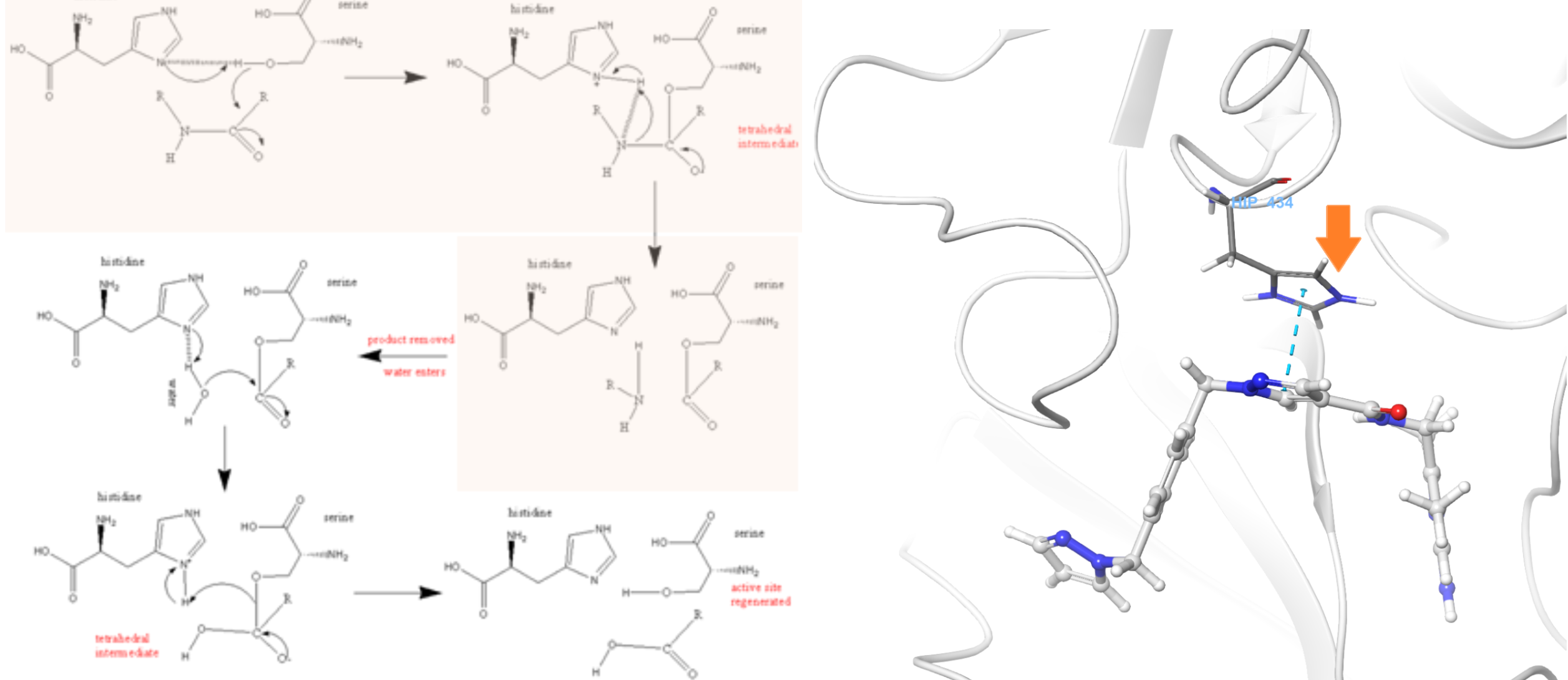
Figure 3. Plasma kallikrein mechanism (left) shows the resting state of this serine protease has a deprotonated HIS434. In its activated form, a proton is transferred from SER578 to HIS, but default preparation leaves the HIS protonated (right). The correct form to be modeled is deprotonated.
Multi-protein constructs — Is your protein active as a monomer, a dimer, or a multimer? Downloading the biological unit for your system might be important if the asymmetric unit structure doesn’t accurately represent the complete biological system (Fig.4)
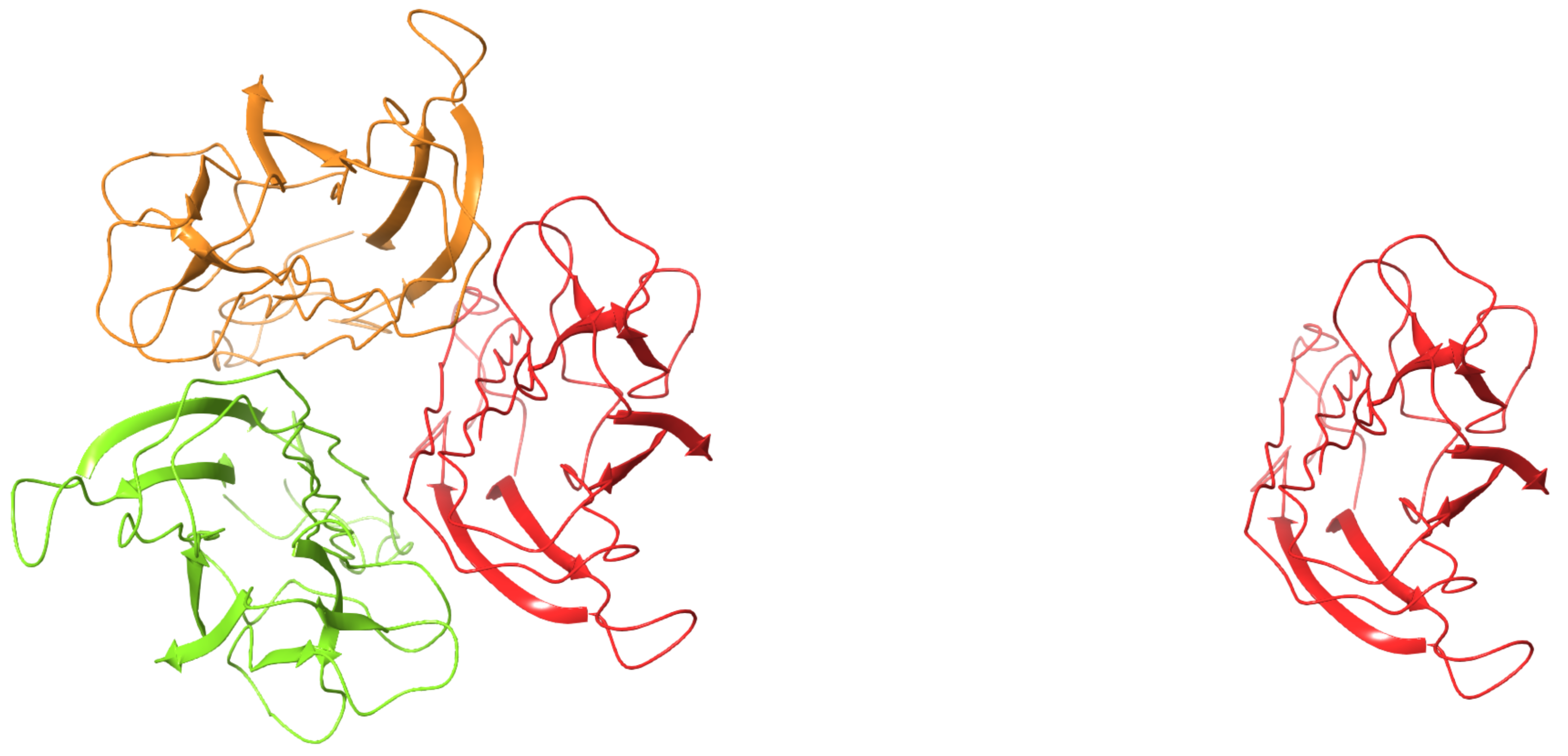
Figure 4. Human TNF-alpha mutant M3S (4TSV) is biologically active as a homo 3-mer (left), rather than a monomer (right)
Download/Examine Other Related Structures
A single structure in isolation might not give a complete picture of your protein: multiple structures may well give a much clearer idea. Consequently, you should consider searching for other structures of your system, overlay these structures in the Maestro workspace and see what they tell you.
Protein mobility — Are any sections of your protein highly variable between the various structures? Understanding what parts are mobile can give you important clues in subsequent modeling: for instance, induced-fit effects are much easier to understand if you already have an idea of what is likely to move within your system (Fig.5).
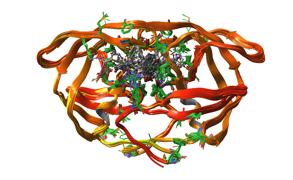
Figure 5. Various HIV-protease entries overlaid to show some structural variation
Typical interactions — If you have a number of different ligands bound to the same protein, you can check whether they make consistent interactions. This will give you some idea of the pharmacophore needed to target that protein, which is clearly vital information for compound design. Additionally, a knowledge of the typical interactions might be critical in assigning protonation/tautomerization states to the structure you are preparing.
Solvent location — Water molecules are frequently quite variable between crystal structures for a variety of methodological and experimental reasons and any given structure may well miss critical solvation or have spurious solvation. Fig. 6, shows an overlay of two PDB structures, 1PNC and 1PND, which are derived from the same high-resolution diffraction data by two independent crystallography teams. Although the protein is placed near identically by both teams, the water structure differs quite substantially.
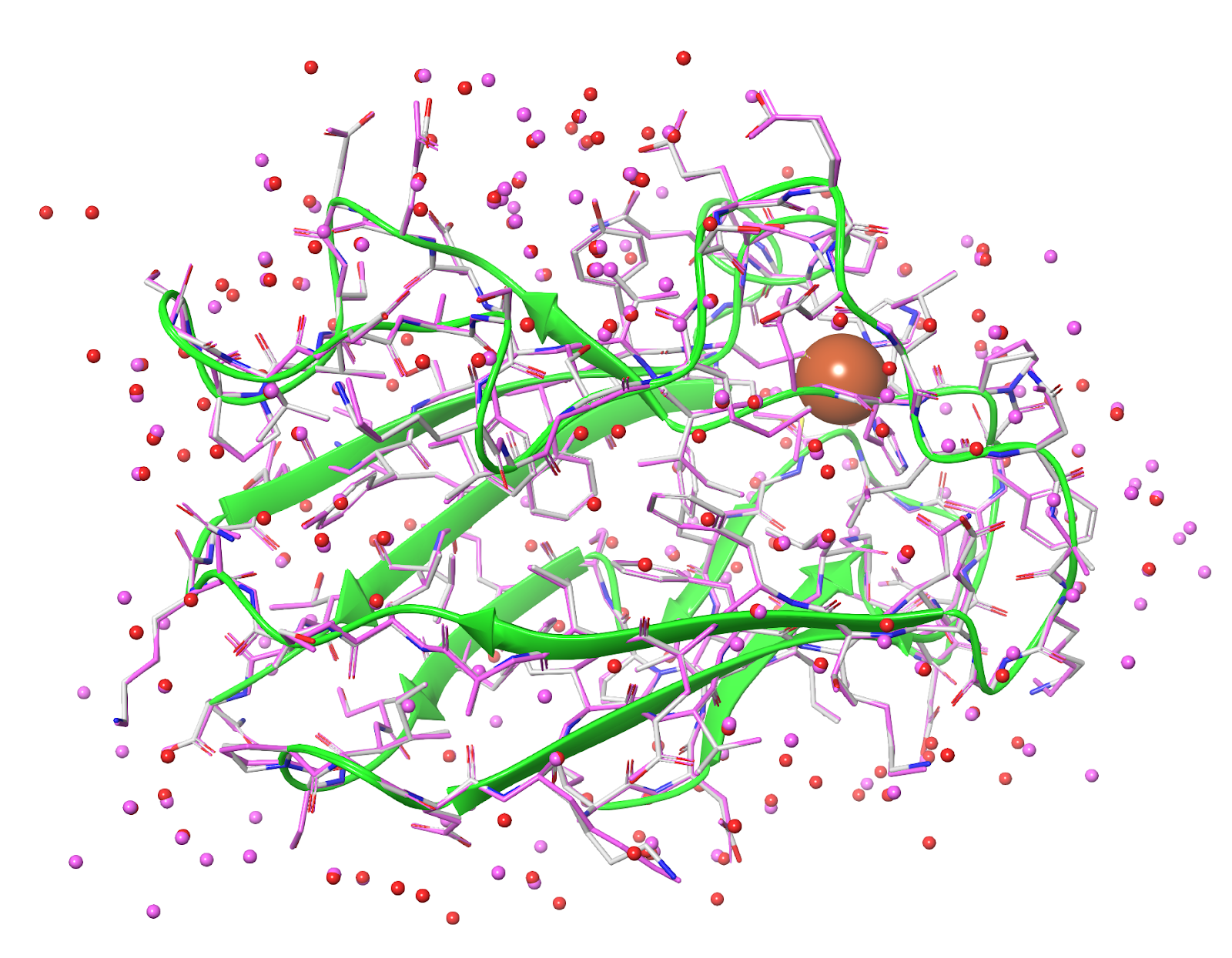
Figure 6. An overlay of 1PNC and 1PND. The red waters come from 1PNC, the magenta waters from 1PND. Despite being derived from the same underlying diffraction data, the water positions differ significantly between the two crystallographic analyses.
By comparing a number of structures one can get a much better idea as to where water molecules are likely to be located and the interactions that they are likely to make. This is not only important for subsequent use of the structure; water molecules can have a profound impact on selecting the correct state of the protein.
Sequence variability — In many instances, the experimentalists will modify the sequence of the protein to aid crystallization. Examining other structures may give some idea as to the effect of these modifications on the underlying structure, yielding information on the reliability of any particular structure. It’s also a good idea to compare the crystallized sequence with the canonical sequence for the protein of interest. This will highlight any other discrepancies and, particularly for proprietary structures, where full PDB records might not be present, issues of missing loops/truncation.
Examine the Underlying Crystallographic Data
X-ray structures are models of the measured electron density and it is important to understand how the crystallographer arrived at the structure you’re trying to prepare. You can gain an idea of the electron-density by either loading in a pre-calculated electron-density map, or by using Schrödinger’s PrimeX tool to calculate the required maps from the underlying diffraction data (Fig. 7).
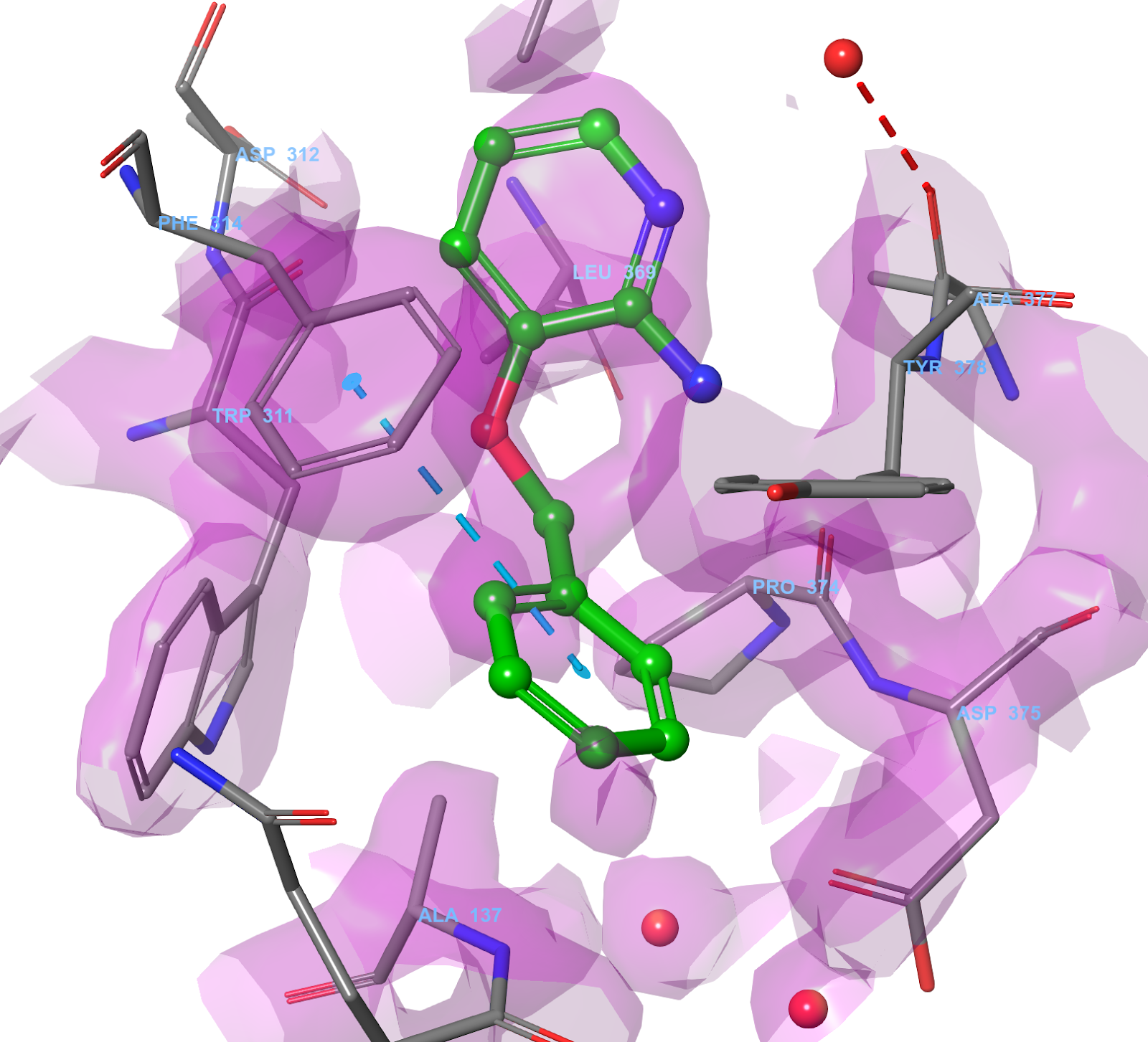
Figure 7. PrimeX, 2Fo-Fc map for 3FTY. Created using the reflection data
Most of your attention should be drawn to the region of interest in the protein you are preparing, typically a ligand binding site; but getting an overall feeling for the complete structure and the sort of data that was used in its creation is important. Generally, you should be keeping an eye out for odd-looking geometries, such as cis-amides, or very close contacts between atoms. High energy features such as this do exist within some systems, but, you will want to ensure that they are supported by unequivocal electron density and are not the result of a misinterpretation by the original crystallographer (Fig. 8). If you have severe doubts about any feature in a structure, it is worth talking to the crystallographer or, if that’s not possible, you could attempt to re-refine the structure yourself using tools such as PrimeX, GlideXtal, or GlideEM.
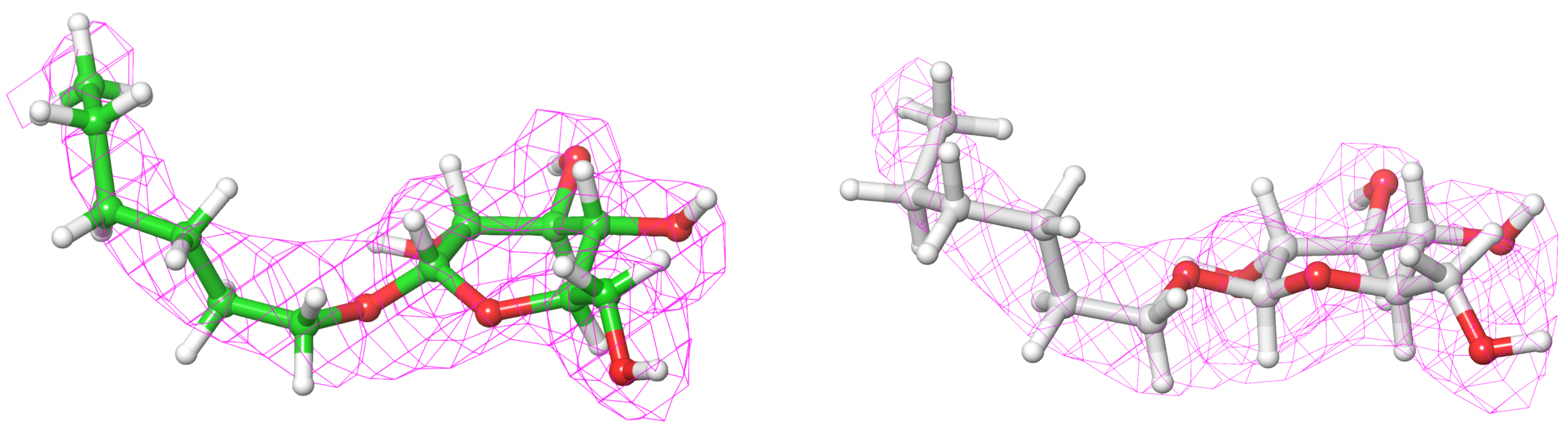
Figure 8. PrimeX 2Fo-Fc map, 2EVS ligand, depicted on the left, and the re-refined PrimeX 2Fo-Fc map, 2EVS ligand is depicted on the right.
The ligand in 2EVS (2.2 A res.) fits the electron density but the ring geometry is poor including an eclipsed torsion (left). PrimeX re-refinement (right) leads to a structure that is both better quality visually and still fits the density well
Another thing to check out at this point is the effect of crystallization on the protein. The crystal lattice is generally a very artificial environment for any protein and contacts between proteins in the crystal can affect the observed conformation. You should definitely be skeptical, for example, if you see crystal contacts interfering with any bound ligand. Fig. 9 shows the structure 1T69: here we can see how the crystal packing allows the bound ligand to come into contact with a second instance of the ligand in the lattice. The conformation of the ligand in this structure must be considered as suspect due to these artificial interactions.
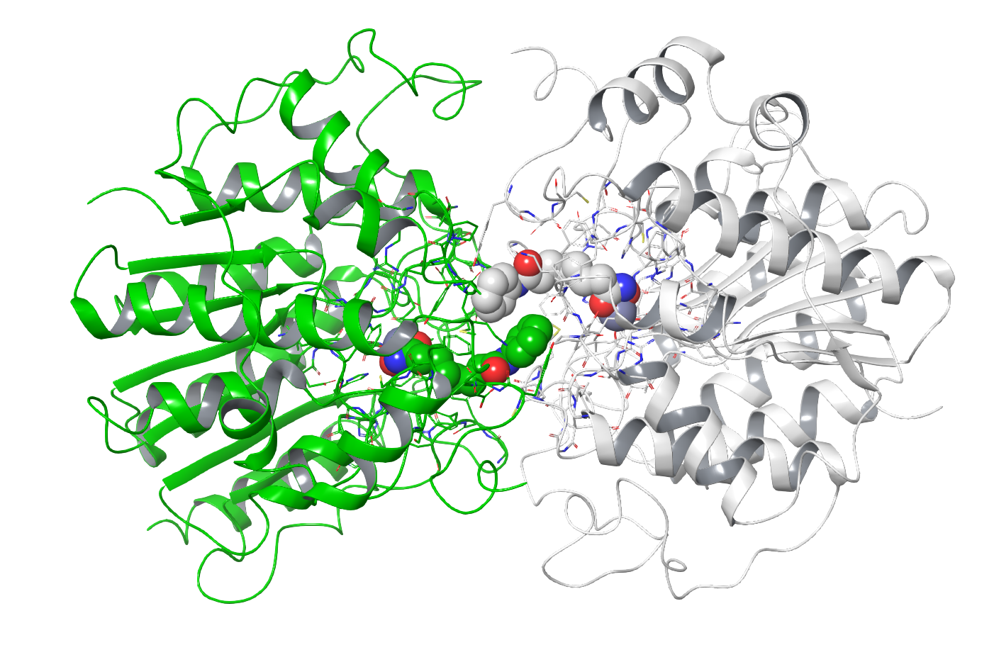
Figure 9. The structure 1T69. The primary image from the PDB is shown in white and a crystal symmetry-related instance is shown in green. The ligands (CPK) of the two instances are making contact with each other. This clearly affects the conformation, making this part of the structure potentially unreliable.
Preparing the Protein
The Protein Preparation Workflow is the primary tool for preparing the protein; here it is referred to as PPW.
Preprocessing the Structure
One should always replace the existing hydrogen atoms on a given structure. They are frequently incorrect and often cause issues in subsequent calculations. PPW-added hydrogens are guaranteed to be compatible with all other programs in the Schrödinger platform.
Preprocessing often brings up some hidden problems in the structure and it is worth reviewing these in the Diagnostics tab of PPW. Many problems can be ignored, such as hydrogen-atom clashes between water molecules and the protein as these will be relieved in subsequent preparation stages. Some clashes, such as bonds going through rings ("ring spears"), cannot be automatically resolved, so you should always check back in the Diagnostics tab after running the PPW to confirm all is well.
Dealing with Missing Parts of the Structure
Whether you need to rebuild missing parts of the structure will depend on the calculations you intend to perform. Roughly, there are two categories of methods in this regard:
- Binding-site focused methods working on static structures (e.g. Glide, SiteMap)
These methods only focus on a specific area/part of the protein and consider the input geometry to be fully rigid. This means that you need to rebuild any missing atoms within the binding site with great attention to detail, as small differences in atom placement there can cause artifacts due to the inability of the system to relax unfavorable conformations. On the other hand, a missing loop at the opposite end of the protein will not affect their results in any way. Frequently, it can be better to leave flexible, badly resolved loops in or near the binding site unmodeled, to avoid problems due to their artificial rigidity. - All-atom MD simulation methods (e.g. Desmond, FEP+, IFD-MD)
These methods require the full protein to be present. All missing heavy atoms or incomplete residues need to be filled in. Chain breaks pose a particular challenge, as unnatural termini can introduce spurious charges unless capped, allow water to enter where it shouldn’t be, change the dynamics of the system, or cause the protein to start unfolding. There are two options for handling protein termini: you can either rebuild the missing parts of the protein, or “cap” the termini to make them neutral. The ends of the sequence should be left charged if they are the natural termini of the protein. If the protein was truncated or there are unresolved residues at the start or end of the sequence, we recommend capping the termini. Whether capping or loop building is the better choice for chain breaks in the middle of the sequence depends on whether the dynamics of the missing part of the structure influence the dynamics of the resolved part on the time scale you are planning to simulate. For example, a chain break separating a different domain from where the binding site is located will probably not affect a 5 ns long FEP+ edge much, but a 500 ns MD simulation probably will be affected.
A bit of caution should be exercised when allowing PPW to automatically build in missing parts of a protein. The addition of a few side chains on the periphery of the protein, well away from any ligand etc. is unlikely to cause a serious issue in many calculations. Larger rebuilds, particularly significant loops, will likely be more accurately carried out separately using other tools such as Prime Homology Modelling, Loop Refinement, and Molecular Dynamics. The issue is that PPW does a quick job of building in these features and their addition tends to get lost in the overall preparation process. Thus, this often does not get scrutinized as thoroughly as it should.
Assigning Appropriate Bond Orders
Generally, PPW is very good at perceiving the correct bond orders within het groups, such as ligands. However, it can fail for odd geometries and bond lengths that sometimes occur in crystal structures (Fig. 10). You should review the assignment of bond orders prior to advancing in the preparation.
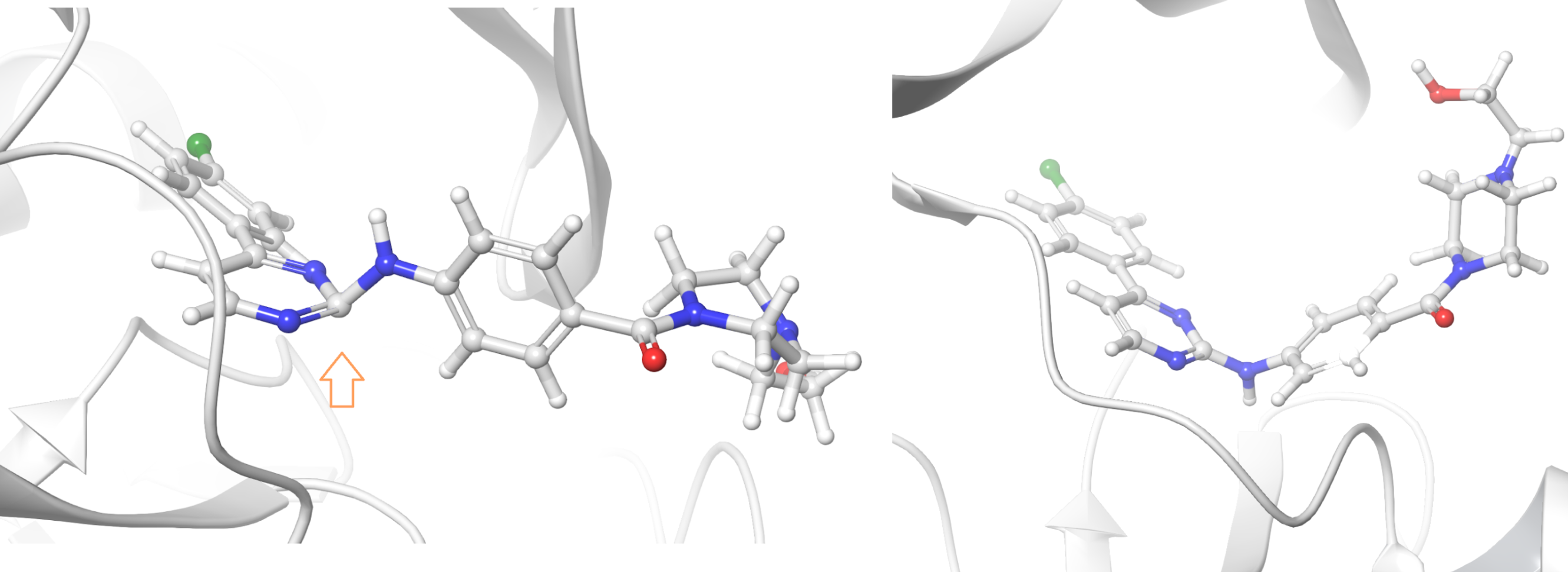
Figure 10. The inhibitor of kappaB kinase beta is badly represented in 3QAD (left) and subsequently redeemed in a more recent deposition, 3RZF (right)
Dealing with Solvent Molecules
You are strongly advised to keep all crystallographically resolved solvent molecules throughout the complete preparation process. Accurate placement of solvent is important for high-level calculations such as molecular dynamics and FEP and while it is very easy to remove excess water from a prepared structure, for example when running a docking calculation, it is much harder to add them back to a system after they’ve been deleted.
If your structure contains structural metal ions, and you are planning to run MD-based calculations, you are strongly advised to ensure they have a complete coordination shell around them, held in place with zero-order bonds. Otherwise, nearby (partial) charges will be drawn to interact with the metal ion, which can disrupt the surrounding hydrogen bond network.
Het Group Preparation
PPW uses parts of Schrödinger’s LigPrep suite to deduce the likely states of any het group within the protein. This is normally quite a reliable process. Nonetheless, you should carefully check that the assigned states are consistent with your understanding of the chemistry of the species involved. If you have doubts about the pKa of a functional group, or the most stable tautomer of a given system, you should explore the various options via the literature, or via pKa/tautomer predictions; Schrödinger’s Jaguar package includes a number of options that can assist with these sorts of considerations.
As noted earlier, you should also consider the charge and oxidation state of any metals present in the binding site.
Protein Protonation Assignment
The PROPKA technology employed by PPW normally does a very good job at assigning protonation states. Nonetheless, you should still pay close attention to its results, particularly within the vicinity of your primary region of interest (e.g. binding site). A few things that are known to cause PROPKA issues include:
Erroneous or missing solvation — PROPKA looks at the environment of any given residue to assess its likely pKa and thus its protonation state. One can run into situations where the environment of a residue is wrong due to missing/inaccurate solvation in the original structure. This results in PROPKA doing a poor job at assigning pKas and ultimately residues being placed in the wrong state. In particular, look out for uncharged Lys-residues; genuine uncharged Lys-residues are very rare in nature and are normally associated with fairly extreme mutations and loss of stability (Fig.11a, 11b). You are unlikely to have one in your protein without it being documented somewhere in the literature, so if PROPKA suggests such a feature, treat it with a large degree of skepticism.
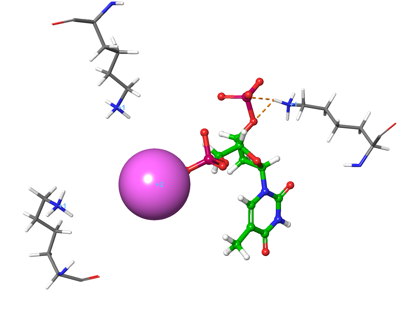
Figure 11a. Charged lysine residues surround the ligand in 2SNM crystal structure, solved at 1.9A resolution
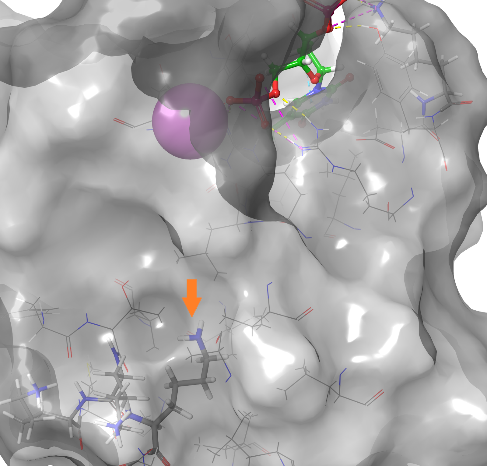
Figure 11b. In a hydrophobic cavity of the same crystal structure 2SNM, V66K, a lysine replacing valine 66, buries its side-chain in the hydrophobic core without salt bridging, hydrogen bonding or other forms of electrostatic stabilization
Small geometry inaccuracies — Small changes in the geometry can cause PROPKA to assess a region quite differently. One area where this manifests itself is in the protonation of Asp/Glu residues due to the close proximity of a pKa perturbing group such as another Asp/Glu or functional group from a ligand. If possible, you should try to prepare a number of similar systems and see how consistent PPW is in these regions. If you have any issues with PROPKA’s assignments, you should be prepared to manually adjust them.
Catalytic residues — As noted previously, many enzymes require residues to adopt unusual protonation/tautomeric states as part of their mechanism of action. PROPKA can sometimes misassign states due to this and the associated geometries involved. You should manually adjust the states of the residues involved to place the enzyme in the desired state.
Post-Preparation Activities
Depending on your intended task, there are a number of post-preparation activities that you should consider:
Comparison with other structures — Looking at the consistency of a variety of prepared structures of the same system will help to highlight some of the potential issues described above.
Manual loop rebuilding — Schrödinger’s Prime package allows you to attempt to rebuild any missing loops. By carrying out this task explicitly, you will get a better appreciation for the loops that need to be built and, potentially, some of the limitations of these modeled features.
Ligand pose refinement — If the ligand pose is questionable, you can use GlideXtal (or GlideEM for cryo-EM structures) to re-place the ligand using density-guided docking.
Additional hydration — Given the unreliability of solvent placement in crystal structure data it makes sense to re-examine the placement of all waters within the system, particularly those in the primary region of interest. Schrödinger’s WaterMap application is useful for placing and evaluating waters using a combination of MD/MC and the highly accurate OPLS3 force-field. A comparison of the holo-WaterMap for any system and the original crystal structure data will show regions of questionable solvation and, occasionally, areas where solvation is clearly missing from the original structure.
Zero-order bonds to metal — It’s worth checking the final coordination geometry of any metal in the system. If the metal has a complete coordination shell with a recognizable geometry (e.g. tetrahedral or octahedral) all is likely well. However, one frequently sees situations where one or more coordination sites are vacant. This can give issues in many calculations and you might want to consider whether a water molecule or other complexing group should be bonded to the metals using zero-order bonds.
Stability assessment — Depending on your ultimate use of the prepared structure, it can be useful to run a modest length molecular dynamics simulation to assess the overall stability of the system. A few hundred ns simulation should not take more than a day on a modern GPU using Desmond and will give valuable information in terms of stability. Things to check include:
-
Protein-ligand interactions — Do the main interactions between the protein and the ligand remain intact throughout the simulation?
-
Significant conformational changes — Is the system simply oscillating around the original crystallographic starting point, or are there more permanent changes to the system? If such changes are present, do they occur in regions that were involved in crystal contacts? Ideally, we’d like our system to be highly stable; however, changes in areas involved in crystal contacts are probably acceptable. More substantial changes indicate some issue with the original structure or possibly the force field. In these cases, further investigation is warranted.
-
Stability around chain breaks or other features — Sometimes it is not possible to build in a missing loop, e.g. if it is just too long. In this case, the model will include a chain break. You should examine the simulation to see if there is any instability in these regions. A small amount of movement in the residues immediately surrounding the break is likely acceptable, particularly if they are distant from your primary region of interest. Large amounts of unraveling, however, are a concern and you should consider carefully whether you wish to proceed with the structure in its current form.
References
-
Figure 1. https://opm.phar.umich.edu/
-
Figure 2. https://www.rcsb.org/structure/3QC4 DOI: 10.2210/pdb3QC4/pdb, https://www.rcsb.org/structure/1oky DOI: 10.2210/pdb1OKY/pdb
-
Figure 3. https://www.rcsb.org/structure/removed/5tz9 DOI: 10.2210/pdb5TZ9/pdb
-
Figure 4. https://www.rcsb.org/structure/4TSV DOI: 10.2210/pdb4TSV/pdb
-
Figure 5. https://pdb101.rcsb.org/motm/6
-
Figure 6. https://www.rcsb.org/structure/1pnc DOI: 10.2210/pdb1PNC/pdb, https://www.rcsb.org/structure/1pnd DOI: 10.2210/pdb1PND/pdb
-
Figure 7. https://www.rcsb.org/structure/3fty DOI: 10.2210/pdb3FTY/pdb
-
Figure 8. https://www.rcsb.org/structure/2EVS DOI: 10.2210/pdb2EVS/pdb
-
Figure 9. https://www.rcsb.org/structure/1T69 DOI: 10.2210/pdb1T69/pdb
-
Figure 10. https://www.rcsb.org/structure/3RZF DOI: 10.2210/pdb3RZF/pdb, Entry 3RZF supersedes 3QAD
-
Figure 11a, 11b. https://www.rcsb.org/structure/2SNM DOI: 10.2210/pdb2SNM/pdb
Glossary
Transmembrane - A transmembrane protein (TP) is a type of integral membrane protein that spans the entirety of the cell membrane. Many transmembrane proteins function as gateways to permit the transport of specific substances across the membrane.
Metalloprotein - Metalloprotein is a generic term for a protein that contains a metal ion cofactor. A large proportion of all proteins are part of this category. For instance, at least 1000 human proteins (out of ~20,000) contain zinc-binding protein domains although there may be up to 3000 human zinc metalloproteins.
MOA - In pharmacology, the term mechanism of action (MOA) refers to the specific biochemical interaction through which a drug substance produces its pharmacological effect. A mechanism of action usually includes mention of the specific molecular targets to which the drug binds, such as an enzyme or receptor.
Fo-Fc map, 2Fo-Fc map - The Fo-Fc map is used to show what has been overfit or not accounted for by the model, while the 2Fo-Fc map will include the Fo-Fc map and electron density around the model. These two maps are then used to correct the model when possible.