IFD-MD Best Practices
Although IFD-MD provides a highly simplified interface (IFD-MD Panel), there are a number of decisions that you can make to incorporate your expertise into IFD-MD's algorithm. This document provides guidance on how to accomplish this.
Identifying Sources of Error For Troubleshooting
The IFD-MD Panel runs jobs in stages, with each stage’s processes being documented in a log file specific to that stage.
The stage log file is an output file which typically appears in the working directory, and provides information on the progress of a run within a given stage. The stage log files also note when each program within an IFD-MD Panel job was completed, as well as listing warnings, errors, and process details.
Should you encounter errors when using the IFD-MD Panel, more information will be found in the stage log file corresponding to the stage in which the error occurred. Log files can be accessed through the Schrodinger command line. The location of a specific stage log file can be found at the start of that stage within the top-level log file.
Deciphering Log Files
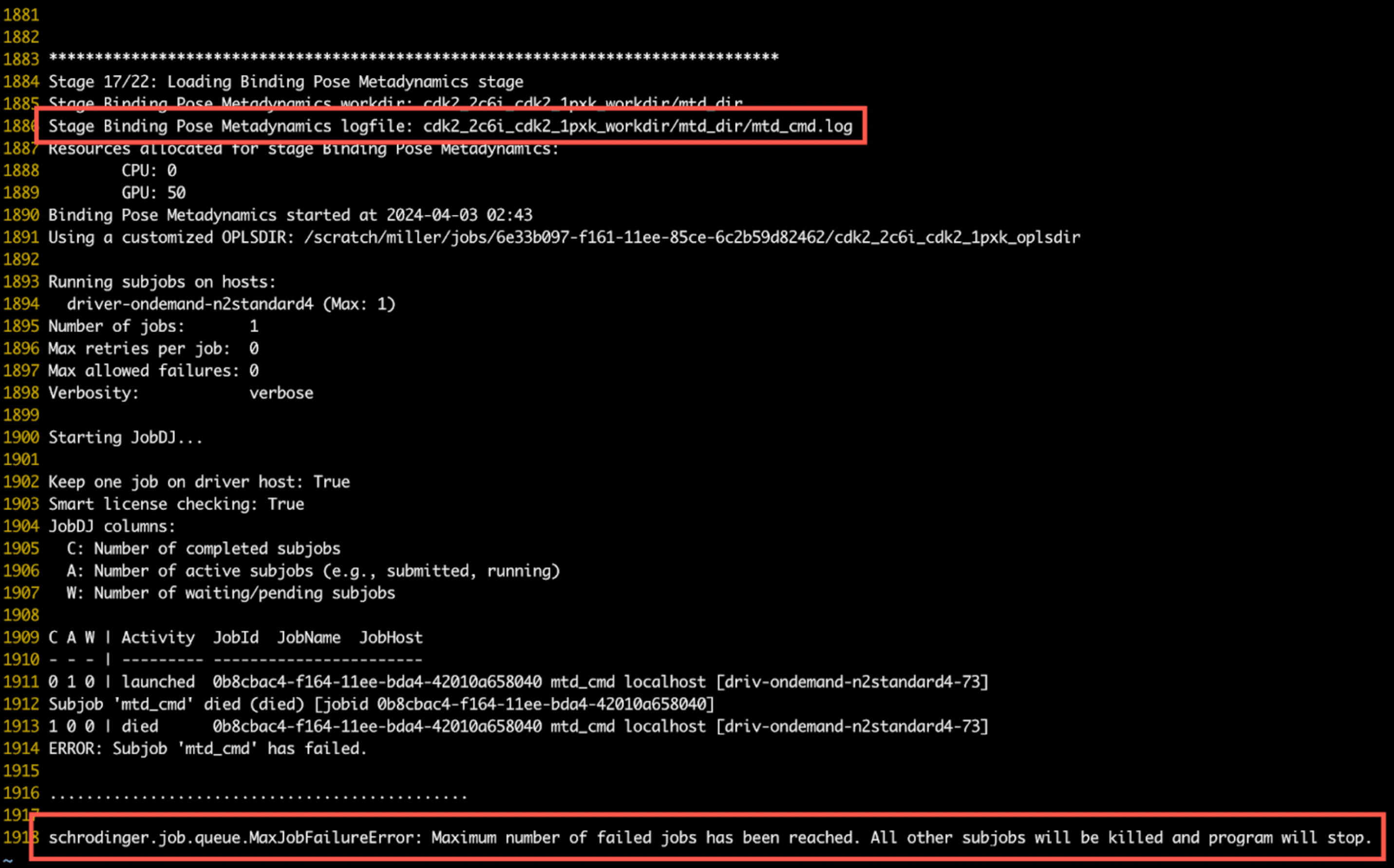
When viewing a log file, the stage information is found at the top of the file. The location of the stage log file can be found at the start of that stage in the top-level log file. Any error messages will appear in the body of the file. In the example below, the error message is shown highlighted at the bottom, with the corresponding stage and log file information is highlighted above it:
On Warning Messages
Warning messages indicate non-fatal errors detected during an IFD-MD run, and often appear as banner notifications in the IFD-MD Panel. These warning messages also appear in a section at the beginning of the stage log file for easy reference.
Warning messages are generated when the conditions for a job are non-optimal, and can provide a starting point when troubleshooting unexpected behavior in a job. For example, when running a job with only one GPU, a warning message will indicate that there are low resources and the resulting job will take a much longer duration.
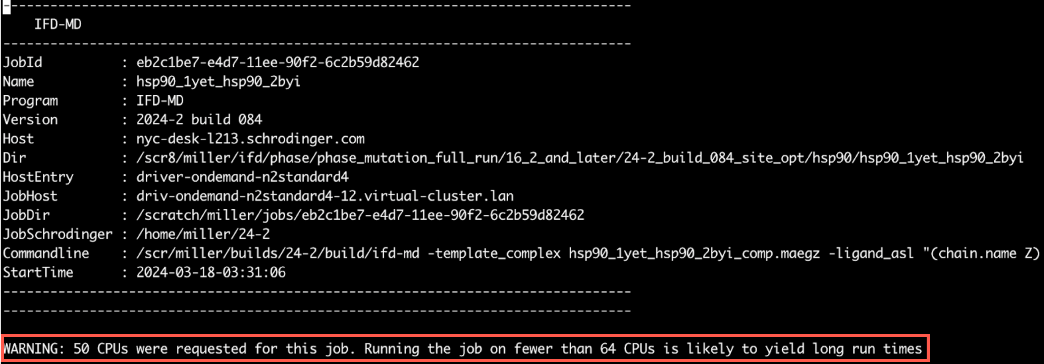
An example of the warning message within a log file is shown below, where the warning message is shown at the top of the log file after the job information:
On Restarting IFD-MD Panel Jobs
To restart an IFD-MD panel job, simply rerun the original command. For reference, the original command used is listed at the top of the IFD-MD logfile next to "Commandline:"
Best Practices by Topic Area
Missing Loops
Summary Guidance: Do not build missing loops.
Explanation: Building missing loops is an option as part of protein preparation. While loops far from the binding site can be built safely, loops near the binding site pose risks for ligand docking and are likely to cause more harm than good. Since the Protein Preparation Workflow Panel does not offer a selection for which missing loops to build, it is advised to not build missing loops prior to running IFD-MD.
Expert knowledge of the system should of course override these considerations but IFD-MD has been shown to be robust even with missing loops located near the binding site. Of the 415 cross-docks that comprised the training and test set, 242 contained at least one missing loop near the binding site (loop stem within 10 Å of the template ligand). For example, the p-loop is not entirely resolved in the binding site of kinases.
Subsequent to IFD-MD, for example just before FEP+ calculations, missing loops should be placed, but the loop would be built in the presence of the IFD-MD docked ligand—this is a crucial difference from building the loop prior to IFD-MD.
Selection of Ligand from Congeneric Series
Summary Guidance: Select the most potent ligand from the series to dock with IFD-MD. If there are multiple iso-potent or near iso-potent ligands, dock the largest one among those with the best affinity.
Explanation: Congeneric series with SAR are highly desirable for validating an IFD-MD model with FEP+. One needs to choose one ligand from the series to dock. The most potent ligand available should allow IFD-MD to identify the most important ligand-receptor contacts. If there are multiple tight binding ligands, the largest ligand would offer the best chance for IFD-MD to sample the binding site, but potency should remain the top criterion.
Selection of Template Ligands
Summary Guidance: Select a template ligand which occupies the same binding site that you expect for your target ligand. The similarity of the template ligand to target ligand is irrelevant and better sampling may be seen if the target ligand is NOT congeneric to the template ligand.
Explanation: The input to IFD-MD is a holostructure. If you have available an existing holoprotein crystal structure of the target of interest with a ligand that binds in a mode similar to what you'd expect your target ligand to bind in, then this is an obvious suitable starting structure for IFD-MD. For example, if you were working with a kinase and trying to obtain the structure of a ligand expected to be a hinge binder, you should ideally pick a crystal structure of the target with another hinge binding ligand.
By chopping up the template ligand, you can suggest to IFD-MD where to focus its sampling. For example, if the template ligand contains an arm occupying a pocket that the to-be-docked target ligand is not expected to visit, then deleting that part of the template ligand would avoid IFD-MD wasting sampling in that pocket.
Selection of Template Ligands for Homology Models
Summary Guidance: If the homology modeling template is of an apo structure or contains an irrelevant ligand in a different binding site, then you will have to manually graft in another template ligand. The template ligand need not be precisely placed and can have severe clashes with the receptor.
Explanation: The homology modeling template may be chosen because of high sequence identity to the target protein. However, the template may not always have a ligand bound. In this situation, you can graft in a suitable ligand. This can be done by taking a holostructure with poorer sequence identity, superimposing the holostructure onto the homology model, and simply placing the ligand from the holostructure into the homology model. This may introduce clashes between the grafted ligand and the homology model. Clashes between the template ligand and starting receptor are perfectly acceptable in IFD-MD and resolving them will be attempted during docking with the target ligand.
Interpretation of the IFD-MD Score
Summary Guidance: The score is only used for the relative ranking of competing poses. The absolute value of the score is not interpretable a a good or bad pose. Smaller values are better, but positive values do not indicate a problem. A score difference between two poses should be larger than 1.5 kcal/mol to be considered significant.
Explanation: The IFD-MD score is only used for the relative ranking of competing poses so there is no absolute number that indicates a good or bad pose. Lower scores are better, but a positive score does not indicate failure. A score difference of 1.5 kcal/mol or larger should be considered significant, and a score difference less than that is insignificant. For example: if the top two poses have a score that differ by less than 1.5 kcal/mol, the IFD-MD scoring function is not able to reliably rank which pose is superior.
One term can indicate that your pose is unlikely to be correct: the metadynamics pose score. In the output csv file, this is the "pose_score" column. In the -out.maegz file produced by IFD-MD, the "pose_score" can be seen in the project table under the IFD-MD secondary properties. This term is in units of Ångstrom and indicates the stability of the pose over 10 ns of metadynamics with the collective variable set to be the ligand RMSD. The smaller this term, the better the ligand can resist the perturbation away from its starting position. We have not seen a native-like pose have a metadynamics pose score larger than 2.5 Å for a ligand which binds tighter than 10 µM. Weak ligands may violate this 2.5 Å pose score. An incorrect pose can still have a value smaller than 2.5 Å, those ligands can be kinetically trapped for example, but a value larger than 2.5 Å should be seen as indicative of a poor quality pose.
Recommended Number of CPUs and GPUs
Summary Guidance: Each user should request as many CPUs and GPUs as there are licenses. If licenses permit, 128 CPU and 64 GPU scales well.
Explanation: IFD-MD sub-jobs are only ever single CPU or single GPU jobs. The number of CPUs and GPUs requested simply control the number of single CPU or single GPU jobs that are simultaneously launched to the queue. Furthermore, the individual subjobs are each short, 30 minutes to an hour long, and will therefore not crowd sub-jobs from other workflows.
Built into IFD-MD is the careful use of license checking to ensure that sub-jobs are safely held in the queue if insufficient licenses are available. That means if there are, for example, only 64 IFD-MD tokens (which supports one IFD-MD job using 64 CPUs), two users can still each safely launch their own IFD-MD jobs, each requesting 64 CPUs. In this example, the total number of CPUs requested (64 + 64) will not be able to run simultaneously but the queuing system will ensure maximal utilization of the licenses as the individual IFD-MD sub-jobs run asynchronously. The user should focus on scientific pursuits, not compute resource utilization.