Crosslink Polymers Viewer Panel
Display and analyze the results of a cross-linking calculation. The panel provides the ability to color structures in the Workspace according to features relevant to the cross-linking calculation, and show plots as a function of time and histograms as a function of molecular weight of various properties.
To open this panel, click the Tasks button and browse to Materials → Classical Mechanics → Crosslink Polymers → Crosslink Polymer Results.
To open this panel from the entry group for the results of a crosslink polymers job, use the Workflow Action Menu  .
.
The following licenses are required to use this panel: MS Maestro
- Features
- Additional Resources
Crosslink Polymers Viewer Panel Features
Job loading buttons
Load or reload the results of a Crosslink Polymers job into the viewer using these buttons.
- Load New Job
-
Load the results of a job into the viewer. Opens the Load Crosslink Polymers dialog box, which gives you two options for locating the results.
-
Load from job database—Select a job from the job database. The table below is loaded with the relevant information from the job database. Select the row in the table for the job you want to look at, and click OK. You can select a running job or a completed job.
-
Manually locate job directory—Specify the path to the job directory, or browse to the directory
-
- Refresh Current Job
-
Reload the results of the current job. This button is useful if you selected a running job to load into the viewer. The latest results are retrieved and loaded into the viewer.
Summary tab
In this tab, the log file for the Crosslink Polymers job is displayed.
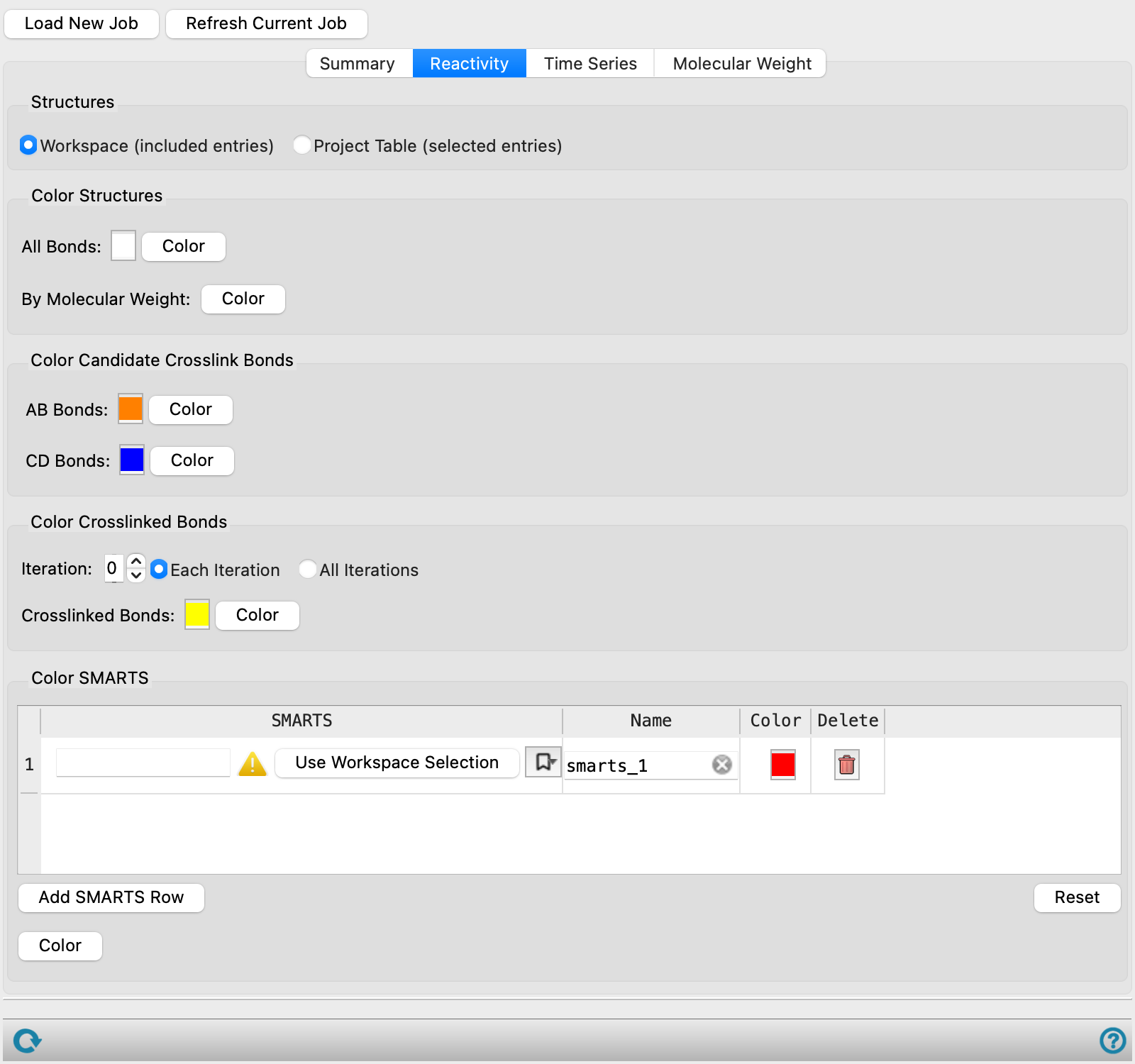
Reactivity tab
Color the structures or parts of the structures that are related to the crosslinking process. Many of the options have a color square that you can click to change the color in a color chooser, and a Color button that you use to apply the color to the structures.
- Structures options
-
Select the source of the structures to color.
-
Workspace (included entries)—Apply the coloring to the entries that are included in the Workspace. This allows you to color just one of the structures returned from the job.
-
Project Table (selected entries)—Apply the coloring to the entries that are selected in the Project Table. If you have all the entries from the cross-linking job selected, this allows you to color them all in the same way.
-
- Color Structures section
-
This section provides tools for coloring the entire structure.
-
All Bonds—Select a color to apply to all bonds in all molecules by clicking the color square. Click Color to apply the color to the structures.
-
By Molecular Weight—Apply a color to each molecule according to its molecular weight. The molecular weights are binned and a color is applied to molecules in each bin, chosen from a set of n colors.
-
- Color candidate Cross-Link Bonds section
-
Color bonds that are candidates for cross-linking but have not yet been selected for cross-linking. You can color the AB and CD bonds separately (the two bond types that can be broken, see the Define reaction section in the Crosslink Polymers topic). The SMARTS pattern for these bonds is reported to the right of the Color button.
- Color Cross-Linked Bonds section
-
Color bonds that have already formed cross-links. The coloring is done on for cross-links that are formed in (or up to) a particular iteration of cross-linking. The iteration is set in the Iteration box. There are two options for applying the coloring:
-
Each iteration—Color the bonds for the specified iteration. This option allows you to color the bonds for a particular iteration, so you could for example color the bonds for each iteration with a different color.
-
All iterations—Color the bonds for all iterations up to and including the selected iteration with the specified color.
Choose the color by clicking the color patch, and apply the color by clicking the Color button.
-
- Color SMARTS section
-
Color atoms and bonds that match specified SMARTS patterns. Each pattern is stored in a row of the table. To add a row, click the Add SMARTS Row button; to delete a row, click the button in the Delete column.
To specify the SMARTS pattern, enter it into the text box in the SMARTS column, or select atoms in the Workspace and click Use Workspace Selection. Click the bookmark icon (
 ) to use a previously saved SMARTS pattern or save the current SMARTS pattern. A dialog box opens, in which you can name the SMARTS pattern. The pattern is added to the menu, and is saved for future Maestro sessions in your Schrödinger user resources directory.
Click the color patch to choose a color.
The SMARTS patterns that you specify here are used in other places, for example in the plots, or exported to a CSV file. You can provide a name for the SMARTS pattern for identification where it is used, in the Name column.
The Reset button below the table clears the data from the table and resets it to the defaults.
Time Series tab
In this tab you can plot various quantities as a function of the progress of the cross-linking.
- X property options
-
The X property represents the reaction time, expressed in terms of either the number of cross-linking iterations (Iteration) or the cross-link saturation (% xlink saturation).
- Y Properties option menu
-
This option menu provides a list of all the properties you can plot. You can choose multiple properties from the menu. All of the properties are plotted on the same scale, shown on the left of the plot, so you should choose properties that have common units or a common range of values. If you want to plot properties that have different units or ranges, you can use the Second Y property option and menu.
To reset the plot to the default option (the density) click the Reset button on the menu.
-
The properties available and their descriptions are as follows:
-
Property Description Stretch Energy (kcal/mol) The bond stretching component of the total energy averaged over the last 10% of MD simulation frames. Torsion Energy (kcal/mol) The dihedral/ torsion component of the total energy averaged over the last 10% of MD simulation frames. Kinetic Energy (kcal/mol) The kinetic energy of all atoms in the system averaged over the last 10% of MD simulation frames. Potential Energy (kcal/mol) The potential energy of the system averaged over the last 10% of MD simulation frames. Total Energy (kcal/mol) The sum of the kinetic and potential energies as described above. Pressure (bar) The pressure of the system during the MD simulation. Volume (Å3) The total volume of the system averaged over the last 10% of MD simulation frames. Density (g/cm3) The density calculated from the total mass and volume of the system averaged over the last 10% of MD simulation frames. # xlinks The number of new crosslinks formed per iteration. Total #xlinks The cumulative number of crosslinks formed. % xlink saturation The percentage of crosslinking sites that have formed crosslinks. First Largest Reduced MW The molecular weight of largest molecule divided by total system weight. Second Largest Reduced MW The molecular weight of the second largest molecule divided by total system weight. Free Volume (%) The percentage of the system volume accessible to a probe sphere calculated using the grid-based Monte Carlo method. This value is helpful for understanding the system's permeability. Use the Free volume compute option in the Crosslink Polymers Panel to calculate this data. Crosslink density (mol/cm3) The concentration of crosslinks in the system calculated by dividing the Total #xlinks by the Volume. Avg. MW between xlinks (g/mol) The average molecular weight between crosslink points. It is calculated by dividing the molecular weight of the crosslinked molecules by the Total #xlinks. The molecular weight of the crosslinked molecules is the sum of the molecular weights of all molecules that contain at least one bond formed by the crosslinker. This value is helpful for determining the crosslink spacing in the system. - Second Y property option and menu
-
Select this option to plot a second property, with the axis shown on the right of the plot. This allows you to plot properties with different scales or units. Only one property can be chosen from this menu.
- Toolbar
-
This is a standard plot toolbar, described in the Plot Toolbar topic.
- Plot area
-
The plot area displays the plots of the selected properties and a legend. The legend can be repositioned by dragging it to the desired location.
Molecular Weight tab
This tab shows a histogram of properties as a function of molecular weight for individual iterations in the cross-linking process.
- Iteration box
-
Choose the iteration for which the histogram is displayed.
- Property option menu
-
Choose the property to display on the Y axis. If you choose Frequency, a histogram of the frequency of occurrence of the particular molecular weight is shown.
- Toolbar
-
This is a standard plot toolbar, described in the Plot Toolbar topic.
- Plot area
-
This area displays the histogram. No changes can be made to the plot.
Status bar
 to reset the panel to its default settings and clear any data from the panel.
If you can submit a job from the panel, the status bar displays information about the current job settings and status for the panel. The settings include the job name, task name and task settings (if any), number of subjobs (if any) and the host name and job incorporation setting. The job status can include messages about job start, job completion and incorporation.
The status bar also contains the Help button  , which opens an option menu with choices to open the help topic for the panel (Documentation), launch Maestro Assistant, or if available, choose from an option menu of Tutorials. If the panel is used by one or more tutorials, hover over the Tutorials option to display a list of tutorials. Choosing a tutorial opens the tutorial topic.