Torsion Profile Analysis Panel
Analyze profiles of torsional angles, as specified by SMARTS patterns, for graphical display.
To open this panel: click the Tasks button and browse to Materials → Tools → Torsion Profile Analysis Calculations.
The following licenses are required to use this panel: MS Maestro
- Using
- Features
- Additional Resources
Using the Torsion Profile Analysis Panel
This panel is mainly intended for the analysis of torsion profiles in polymers, for example to find torsions that create kinks during a simulation. If the structure input has periodic boundary conditions and an associated trajectory for analysis, you can do the analysis over the simulation time. The analysis can be done for coarse-grained systems as well as atomistic systems.
To visualize the results, you can use the Torsion Profile Analysis Viewer Panel ( click the Tasks button and browse to Materials → Tools → Torsion Profile Analysis Results). To open this panel from the entry group for the results of a job .
.
Torsion Profile Analysis Panel Features
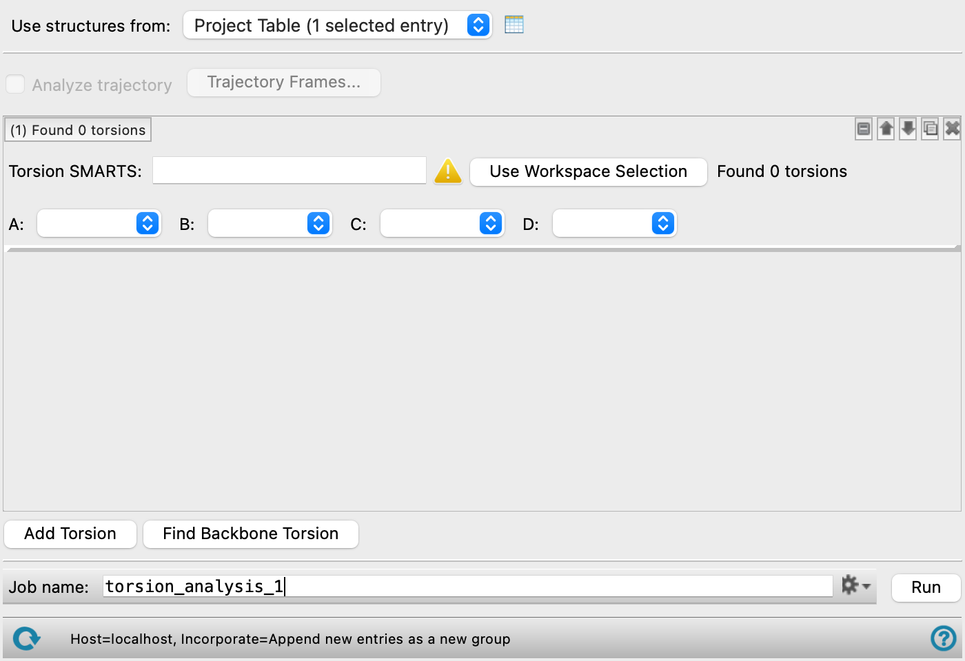
- Use structures from option menu
-
Choose the structure source for torsion profile analysis.
- Project Table (n selected entries)—Use the entries that are currently selected in the Project Table or Entry List. The number of entries selected is shown on the menu item.
- Workspace (n included entries)—Use the entries that are currently included in the Workspace, treated as separate structures. The number of entries in the Workspace is shown on the menu item.
- Project Table (n selected entries)—Use the entries that are currently selected in the Project Table or Entry List. The number of entries selected is shown on the menu item.
- Open Project Table button
-
Open the Project Table panel, so you can

- Analyze trajectory option
-
Analyze the frames in the trajectory associated with the structure. This enables plotting of the profile as a function of simulation time in the Torsion Profile Analysis Viewer Panel. This option is not available if the input structure does not have periodic boundary conditions and a trajectory.
- Trajectory Frames button
-
Set the range and interval of trajectory frames to use in the analysis. The total number of frames to be used and the time range (in ns) corresponding to the selected frames are shown to the right of the button. Opens the Trajectory Frames dialog box, in which you can set the following:
-
- Frame range text boxes—Set the range of frames to use. You can also use the slider to select the range.
- Step size text box—Set the interval at which trajectory frames are taken. For a step size of n, every nth frame is taken within the selected range. The first and last frames are always included. Increasing the step size decreases the number of frames to be used and the computational time needed.
- Frames text—Lists the corresponding frame numbers of the selected frame range and step size.
- Time text—Lists the corresponding time range and interval (in ns) of the selected frame range and step size.
- OK button—Apply the selected trajectory frame range and step size and close the dialog box.
- Torsion definition tools
-
These tools allow you to define torsion types in terms of SMARTS patterns. All torsions defined by the SMARTS pattern are included in the analysis.
- Torsion label and count text
-
This text identifies the torsion by number and reports the number of torsions found. Clicking on it shows or hides the torsion definition tools.
- torsion definition management buttons
-
These buttons perform display and ordering operations on the torsion definition. They allow for easy duplication and rearrangement of torsion definitions.


Show or hide the contents of the torsion definition. When hidden, only the torsion definition number, label (if any) and these buttons are displayed. This is useful when you have a number of torsion definitions and want to compare two separate torsion definitions, for example. 

Move the torsion definition up or down one place in the list. 
Duplicate the torsion definition. This is useful for creating similar torsion definitions with variations on the settings. 
Delete the torsion definition. - Torsion SMARTS text box and
-
Enter the SMARTS pattern for defining the torsional angle in the text box, or select the atoms in the Workspace for the SMARTS pattern and click
- Torsion atom option menus A, B, C, D
-
Select the atoms from the SMARTS pattern that define the torsion A-B-C-D. The menus are populated from the SMARTS pattern and a default selection is made.
- Add Torsion button
-
Add a set of torsion definition tools below the last set.
- Find BackboneTorsion button
-
Find the torsion for the backbone of the structure and add a torsion definition tool set. The SMARTS pattern is populated automatically. The backbone is defined as usual for structures such as polymers and proteins; for other structures it is the shortest path between the farthest non-hydrogen atoms in a molecule.
- Job toolbar
-
Manage job submission and settings. See Job Toolbar for a description of this toolbar.
The Job Settings button opens the Torsion Profile Analysis - Job Settings Dialog Box, where you can make settings for running the job.
- Status bar
-
 to reset the panel to its default settings and clear any data from the panel.
If you can submit a job from the panel, the status bar displays information about the current job settings and status for the panel. The settings include the job name, task name and task settings (if any), number of subjobs (if any) and the host name and job incorporation setting. The job status can include messages about job start, job completion and incorporation.
The status bar also contains the Help button
 , which opens an option menu with choices to open the help topic for the panel (Documentation), launch Maestro Assistant, or if available, choose from an option menu of Tutorials. If the panel is used by one or more tutorials, hover over the Tutorials option to display a list of tutorials. Choosing a tutorial opens the tutorial topic.