Covalent Docking Panel
Dock a set of ligands to a receptor, in which the ligands form a covalent bond to a receptor residue or site by a specified type of reaction (such as a Michael addition). The ligands must all contain the reactive group, which is specified by a SMARTS pattern.
To open this panel: click the Tasks button and browse to Receptor-Based Virtual Screening → Covalent Docking.
- Overview
- Using
- Features
- Additional Resources
Covalent docking has two main goals:
- Locate the best docked pose for each ligand and rank the poses for each ligand by energy.
- Rank ligands according to the ability of the ligand to bind noncovalently in a suitable pose for reaction to form a covalent bond.
The ligands must be a series of related compounds, all of which react with the receptor at the same site and by the same mechanism. Use of covalent docking to compare different mechanisms or different types of compound will not produce meaningful results.
The covalent docking process has several stages:
-
Dock the ligands into noncovalently bound poses that are suitable for covalent bond formation. To allow for different possible conformations of the side chains of the reactive residue, it is mutated to alanine in this stage. This removes any bias towards a particular ligand conformation that would occur if the side chain were regarded as fixed. The ligands are docked with Glide, subject to constraints between the attachment atoms on the receptor and the ligand.
-
Form the bond between the receptor and the ligand. First, the reactive residue side chain is restored, and its rotamers are sampled to find the best conformation for each ligand pose. The bond is then formed and poses are discarded if the ligand-receptor bond is too long. The ligand and reactive residue, now covalently bound, are then minimized and the poses clustered.
-
Minimize and rank the poses. After clustering, a representative pose is selected from each cluster, and the poses are minimized with Prime. The poses for each ligand are then ranked by the Prime energy.
-
Score poses for the affinity of the ligand to the receptor for noncovalent binding prior to reaction. Ligands that do not score well are considered less likely to approach the receptor in a way that permits covalent bond formation. In this stage, the bond is broken again, the reactive receptor residue is mutated to alanine, and the bond to the ligand is capped with hydrogen. Scoring is then done with Glide, and the affinity is reported as the average of the pre-reacted and post-reacted GlideScore for a given pose.
There is also a virtual screening mode, in which rotamer sampling and minimizations are not performed, and ligand sampling is reduced. The affinity score and the Prime MM-GBSA energy are not calculated, as the poses are not accurate enough, but the docking score can be used to filter the poses.
Reaction Types
The reaction type defines the functional group on the ligand that reacts, the allowed residue types or groups in the receptor with which the ligand can react, the atom in the ligand that becomes bonded to the receptor, and the operations that must be performed on the structures to create the covalent bond. The ligand functional group is represented by a SMARTS pattern, with an atom index that identifies the atom that forms the bond with the receptor. When the ligands are docked, all patterns are tried for a match to the ligand, and each match is docked, which could include multiple matches on a single ligand.
The reaction types, the ligand functional groups in terms of a SMARTS pattern, and the allowed residue types are given in the table below. The notation R-SH,OH means one of six residues with an SH or OH bond: CYS, SER, THR, ASP, GLU, TYR. The reactive site is not limited to standard residues, however: you can select any group that has the same reaction chemistry as the standard residue. For example, any R-OH group can be used as a reactive site instead of a standard residue that has an OH group.
| Reaction type | Default Ligand SMARTS | Reactive Residues |
|---|---|---|
| Michael Addition | [C,c]=[C,c]-[C,c,S,s]=[O] | R-SH,OH |
| Nucleophilic Addition to a Double Bond | [C,c]=[O,S] | R-SH,OH |
| Nucleophilic Addition to a Triple Bond | [C]#[N] | R-SH,OH |
| Nucleophilic Substitution | [*][F,Cl,Br,I] | R-SH,OH |
| Boronic Acid Addition | [B]([O])[O] | R-SH,OH |
| Epoxide Opening | [C;r3][O;r3][C;r3] | HIS, R-SH,OH |
| Imine Condensation | [C](=[O])-[C] | LYS, ASN, GLN, ARG |
| Phosphonate Addition | [P]-[O;H1,-1] | R-SH,OH |
| Beta Lactam Addition | [O-0X1]=[C]1[C][C][N]1 | CYS, SER |
| Conjugate Addition to Alkene (nitrile activated) | [C,c]=[C,c]-[C,c]#[N,n] | CYS, SER |
| Conjugate Addition to Alkyne (carbonyl activated) | [C-0X2]#[C-0X2][C-0X3]=[O-0X1] | CYS, SER |
| Conjugate Addition to Alkyne (aryl activated) | [C]#[C]-[c] | CYS, SER |
| Disulfide Formation | [S;X2;H1] | CYS, SER |
| Ion Pair to Covalent Bond: Lig(-1)/Rec(+1) | [-1] | LYS, ARG, HIS (HIP) |
| Ion Pair to Covalent Bond: Lig(+1)/Rec(-1) | [+1] | ASP, GLU |
Using the Covalent Docking Panel
To set up a covalent docking run, you must have a receptor that is prepared for modeling and a set of prepared ligands that all have the required functional group for reaction. It is recommended that you use the Protein Preparation Workflow Panel for preparing the protein, and the LigPrep Panel to prepare the ligands. You might also have to filter the ligands to ensure that they all have the required functional group, which you can do in the Ligand Filtering Panel. See Preparing Structures for Covalent Docking for more information.
With these structures available, the process for setting up a default job is described in the steps below.
-
Open the Covalent Docking panel.
-
Choose the source of ligands from the Use ligands from option menu, and if using a file, specify the file.
-
Display the receptor in the Workspace and choose the reactive residue: in the Receptor tab, select Pick and pick a residue in the Workspace.
The reactive residue must be of the correct type for the desired reaction—see the table below for a list of allowed residues.
-
Define the center of the grid box for the Glide docking.
If you want to define the center with a ligand, you must include the ligand in the Workspace.
-
Choose the reaction type: in the Reaction Type tab, select a reaction from the Reaction type option menu.
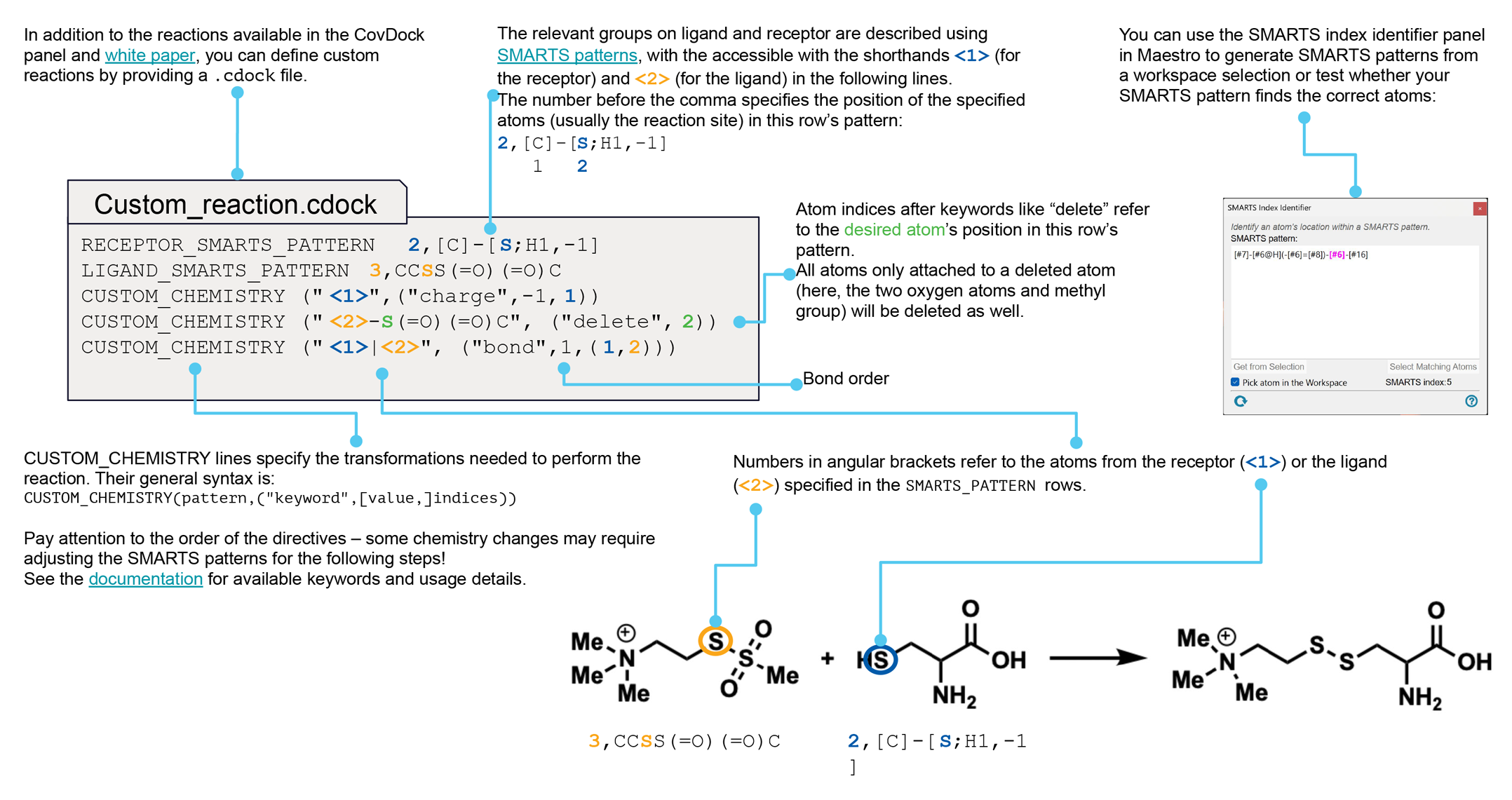
If you want to investigate some other reaction type, you must have a custom chemistry file, which defines all the required quantities. You can make your own custom chemistry file using the procedure described in Custom Chemistry Definitions for Covalent Docking. This feature allows you to specify a reactive site on the receptor other than a standard residue, for example.
-
(Optional) Edit the SMARTS pattern for the ligand reactive group, and add SMARTS patterns, or import a set of SMARTS patterns defined previously.
The default SMARTS pattern is generic and minimal, and might match groups on your ligands that you do not want to consider. Editing the default pattern and adding other patterns allows you more control over the matching. It may be useful to have a ligand displayed in the Workspace on which you can select atoms for the SMARTS pattern that define the functional group.
To edit or add SMARTS patterns, click Edit or New, and modify the SMARTS pattern directly, or pick atoms in the Workspace to define the group and click Get From Selection. Choose an atom in the SMARTS pattern from the Position option menu as the reactive atom, and click OK
-
In the Docking tab, choose a docking mode: Pose prediction for the most thorough treatment, or Virtual screening, for a faster treatment that can be used on thousands of ligands.
The virtual screening mode leaves out most of the minimization and conformational searching, and is at least 10 times faster. Pose prediction mode can take an hour or two per ligand.
-
Specify the number of output poses per ligand that you want returned.
-
Start the job.
The process can take several hours per ligand. You should therefore consider distributing the job over multiple processors, which you can do by clicking the Job Settings button (gear icon) and choosing the host, the number of processors, and the number of subjobs. The number of subjobs should not be greater than the number of ligands.
The ligands are automatically analyzed for matches to the SMARTS patterns, and reanalyzed when any change is made to the reaction type or the SMARTS patterns. This process is fast, but a warning is posted if you have more than 1000 ligands. A progress bar is displayed for the analysis.
The results of a covalent docking run are the covalently bound poses in a Maestro file, which by default is incorporated into the current project as a new entry group. Each pose has three main properties associated with it: the affinity score, the Prime energy of the pose, and an index that identifies the reactive site on the ligand if the ligand has more than one such site. Since comparing poses is only meaningful for poses bonded at the same site, you can use the index to select and compare poses for a particular site. See also Output from Covalent Docking.
To write out the input file and a script for running the job from the command line, click the arrow next to the Settings button  and choose Write.
Torsional Constraints
There are situations in which you want to constrain some of the torsional degrees of freedom in the ligand. For example, a ligand in the binding site might have only one conformation of a particular rotatable group, while other groups can exist in several conformations. Or the ligand might have a large number of rotatable bonds, such as in a polypeptide. Another example is when your ligand set contains atropisomers. The constraints can be applied to prevent sampling of the torsion that is responsible for the atropisomerism.
The groups that are constrained are defined in terms of SMARTS patterns, and you can constrain all of the torsions in the group or only selected torsions in the group.
To set torsional constraints, first you must define a SMARTS pattern that matches the group on the ligands that you want to constrain (and does not match groups that you do not want to constrain), and then define the torsion or torsions within that SMARTS pattern whose values are to be constrained. You can define more than one group to constrain, and more than one torsion in each group. The basic procedure is:
-
Pick atoms in the Workspace ligand that define the group.
-
Click New.
The New Torsion Pattern dialog box opens.
-
Click From Workspace Selection.
The SMARTS pattern is entered into the text box.
-
Click OK.
The SMARTS pattern is added to the Patterns table and marked on the Workspace ligand.
-
Select an option for the torsions to constrain: All torsions, or Specified torsions.
If you chose Specified torsions, continue with the steps below.
-
Pick four atoms in the SMARTS pattern on the Workspace ligand to define a torsion for the pattern.
The atoms must be in adjacent bonds and not all in a ring. The torsion is added to the torsions table along with the current value of the torsional angle.
-
Choose whether to set the angle to a fixed value for all ligands or to fix the angle independently at the input value for each ligand. You set the angle to a fixed value by selecting the check box in the Set angle column of the table, and editing the Angle table cell to set the desired torsional angle.
Covalent Docking Panel Features
- Use structures from option menu
- Open Project Table button
- File name text box and Browse button
- Receptor tab
- Reaction Type tab
- Core tab
- Constraints tab
- Torsional Constraints tab
- Docking tab
- Job toolbar
- Status bar
- Use ligands from option menu
-
Choose the structure source for the ligands to be docked.
- Project Table (n selected entries)—Use the entries that are currently selected in the Project Table or Entry List. The number of entries selected is shown on the menu item.
- File—Use the specified file. When this option is selected, the File name text box and Browse button are displayed.
- Project Table (n selected entries)—Use the entries that are currently selected in the Project Table or Entry List. The number of entries selected is shown on the menu item.
- Open Project Table button
-
Open the Project Table panel, so you can

- File name text box and Browse button
-
Enter the file name
- Receptor
- Reaction Type
- Core
- Constraints
- Torsional Constraints
- Docking
- Reactive residue text box and Pick option
-
Specify which residue (or site) in the receptor the ligand is bound to. You can pick the residue in the Workspace by selecting Pick and picking an atom in the desired receptor residue, or you can enter the chain name and residue number in the text box, separated by a colon. The residue must be one of those defined by the reaction type—see the table under Reaction Type option menu, below, for a list of allowed residues. It must also have a standard residue name.
Make sure you do not pick a residue in the ligand, if you have it displayed in the Workspace.
- Box center options
-
Specify the center of the docking grid box for Glide docking. The grid box must be approximately centered on the active site.
-
Centroid of Workspace ligand—Center the grid at the centroid of the ligand molecule that is displayed in the Workspace. You must display a ligand in the Workspace as well as the receptor to use this option. Select Pick, then pick a ligand atom in the Workspace. Be careful not to pick the reactive residue in the receptor.
Note: The ligand that you pick is removed from the structure to generate the grid for docking (just as for regular, non-covalent Glide docking).
-
Centroid of selected residues—Center the grid at the centroid of a set of selected residues. This allows you to define the active site (where grids should be centered) with only the receptor in the Workspace. When this option is chosen, the Specify Residues button is activated. This button opens the Active Site Residues Dialog Box, so you can select the residues that best define the active site.
If you use this option, you should not simply select the reactive residue, as the reactive residue can be on the periphery of the binding site. Instead, you should select residues whose centroid is approximately at the center of the binding site. Alternatively, use the Centroid of Workspace ligand option.
-
Supplied X, Y, Z coordinates—Center the grid at the Cartesian coordinates that you specify in the X, Y, and Z text boxes. These text boxes are only active when you choose this option.
When you have specified the box center, the box should be displayed in the Workspace.
-
- Box size options
-
Select an option for determining the size of the grid box.
-
Auto—Automatically determine the size of the grid box. If the Docking box center option is Centroid of Workspace ligand, the enclosing box size is calculated automatically from the size of the ligand. If the Docking box center option is Centroid of selected residues, the enclosing box size is set to a cube with sides of length 26 Å.
-
Dock ligands with length <= N Å—Select this option to set the size of the grid box. Enter the desired side length in the text box, in angstroms. The grid box has sides of equal length given by the value in the text box.
-
- Reaction type option menu
- Custom chemistry file text box and Browse button
- Ligand reactive groups table
- Edit button
- Delete button
- Import button
- Export button
- Reaction type option menu
-
Choose the reaction type from this option menu. The standard reaction types are listed below. If the reaction type that you are interested in is not supplied in the default set, choose Custom (from file) to use a custom reaction type, then import the reaction type definition using the Custom chemistry file text box and Browse button. For instructions on creating a custom reaction type, see Custom Chemistry Definitions for Covalent Docking.
- Custom chemistry file text box and Browse button
-
Specify the name of the custom chemistry file in this text box, or click Browse to navigate to the file. The file must have a
.cdockextension. This text box and button are only available if you choose Custom from the Reaction type option menu. - Ligand reactive groups table
-
The SMARTS patterns that define the ligand reactive group are listed in the table, along with the atom in the pattern that forms the bond to the receptor (Position column). The table also lists the total number of reaction sites over all ligands and the average number per ligand. If these values indicate that some ligands may have more that one reactive site, you might want to edit the SMARTS pattern to provide a more restrictive expression and eliminate unwanted sites.
To remove a pattern from the table, select it and click Delete. If you delete the only pattern in the table, the default pattern is added back to the table.
- Edit button
-
Modify the SMARTS pattern for the reaction. You may want to do this to create a more specific pattern, as the default SMARTS pattern for the ligand is generic. You might want to use more specific SMARTS patterns to apply additional criteria beyond the actual reactive functional group, for example.
The SMARTS pattern cannot be edited directly in the table. The button opens the Edit Reactive Group Dialog Box
Once you have edited the default SMARTS pattern, you can add more patterns. The button changes from Edit to New.
- Delete button
-
Delete the selected SMARTS pattern from the table. If you delete the last remaining pattern, the default pattern is restored.
- Import button
-
Import a set of SMARTS patterns from a file in CSV format. The file must contain the SMARTS pattern in the first field, and the atom number of the reactive atom in the second field. Opens a file selector, so you can navigate to a location and select the file.
- Export button
-
Export the SMARTS and Position columns of the table to a CSV file. This allows you to store patterns that define a reactive group for later use. Opens a file selector, so you can navigate to a location and name the file.
- Restrict docking to reference position option
- Workspace ligand option, text box and Pick option
- Reference file option, text box and Browse button
- Tolerance text box
- Maximum common substructure option
- All heavy atoms option
- All atoms option
- SMARTS pattern option and text box
- Get from Selection button
- Restrict docking to reference position option
-
Restrict the docking of ligands so that the ligand "core" lies within a given RMSD of the core in the reference ligand. The core is defined in terms of a set of atoms or a SMARTS pattern; if the ligand does not contain these atoms, it is skipped.
- Workspace ligand option, text box and Pick option
-
Use the Workspace ligand for the reference ligand. If you used a ligand to define the grid, this ligand is chosen by default. The identity of the ligand is shown in the text box. If you want to use a different ligand, add it to the Workspace, then select Pick and pick the ligand in the Workspace.
- Reference file option, text box and Browse button
-
Use the first ligand in the specified file as the reference ligand. Click Browse to navigate to the file, or enter the file name in the text box. You must ensure that the structure in the file is positioned properly with respect to the receptor.
- Tolerance text box
-
Tolerance in angstroms for the RMSD of the docked ligand core to the reference core. If the RMSD is less than this tolerance, the ligand is skipped.
- Maximum common substructure option
-
Use the maximum common substructure of the ligand that is being docked and the reference ligand to define the core atoms.
- All heavy atoms option
-
Use all non-hydrogen atoms in the reference ligand as the core atoms.
- All atoms option
-
Use all atoms in the reference ligand as the core atoms.
- SMARTS pattern option and text box
-
Define the core atoms in terms of a SMARTS pattern. You can pick atoms in the Workspace and click Get From Selection to define the SMARTS pattern, or you can type a SMARTS pattern into the text box.
- Get from Selection button
-
Select atoms in the Workspace, and click this button to define a SMARTS pattern from the selection. The SMARTS pattern replaces the content of the SMARTS pattern text box.
- Positional/NOE subtab
- H-bond/Metal subtab
- Ligand Feature column
- Edit Feature button
- Delete and Delete All buttons
- Must match options
- Positional/NOE subtab
-
This subtab provides tools for defining positional and NOE (nuclear Overhauser effect) constraints. Positional constraints are defined as spheres that specified atoms of the ligands must occupy. NOE constraints are similarly defined as spherical shells (the region between two spheres) that specified atoms of the ligands must occupy.
- Positions table
-
This table displays the positional constraints you have chosen, giving the name and coordinates of the sphere center. For positional constraints a maximum distance is shown, which is the radius of the constraint sphere; for NOE constraints a minimum and a maximum distance are shown. The coordinates and the radius are given in angstroms. You can select a single constraint in the table, and edit the coordinates and radii of the spheres by clicking in the table cell and changing the value, or delete the constraint by clicking the Delete button. If you want to convert a positional constraint to an NOE constraint, you can do so by providing a minimum distance.
- New button
-
To add a positional constraint or an NOE constraint, click the New button. This button opens the New position/NOE dialog box, in which you can pick atoms with the standard picking controls to define the centroid of the constraint; name the constraint; select the constraint type (Position or NOE); specify the radius for a positional constraint, or the minimum and maximum distance for an NOE constraint. The position is the centroid of the selected atoms, and must be inside the enclosing box. While picking is in progress, the constraint is marked with a gray sphere. For NOE constraints, both spheres are displayed. When you click OK, the constraint is added to the table if it is inside the enclosing box; otherwise a warning is displayed.
- Show markers option
-
This option is selected by default. The selected constraint is marked by one or two yellow spheres, depending on the constraint type. The other positional or NOE constraints are marked by red spheres. Deselect this option to remove the markers.
- Label positions option
-
This option is selected by default. If Show markers is selected, this option displays the name of the constraint in the Workspace. The labels are colored the same as the constraints. Deselect this option to remove the labels.
- H-bond/Metal subtab
-
The H-bond/Metal subtab contains controls for setting up hydrogen-bonding or metal constraints. These constraints are made to individual atoms, which can be picked in the Workspace.
- Receptor atoms table
-
As you select atoms in the receptor, they appear in this table. Each constraint is identified by a name and an atom specification. A default constraint name is supplied. You can change the name by editing the table cell. The atom specification is given in the following format:
atom_number:chain: residue_name residue_number : atom_name : symmetry_set
where
- atom_number = Maestro atom number
- chain = chain name
- residue_number = residue number + insertion code
- atom_name = PDB atom name
- symmetry_set = atom name or symmetry-equivalent atom set
For example:
341:C:ASN 239 : OD1: OD1
If the picked atom is part of a symmetry-equivalent set, its identification is followed by square brackets enclosing the number and name of each atom in the set, separated by commas:
2203:C:GLU 192 : OE2:[2203: OE2,2202: OE1]
The default constraint name is
chain:residue_name:residue_number:atom_name(type)where the quantities except type are defined above, and type is eitherhbondormetal, for example,C:ASN:239:OD1(hbond)
The Use Symmetry column indicates whether symmetry-equivalent atoms are included with the picked atom for a constraint or not. Symmetry can be turned on or off by selecting or clearing the check box in this column. If you clear the check box, only the atom that you pick is used for the constraint, and the symmetry information is removed from the Atom column. Symmetry is on by default.
- Pick atoms option
-
When this option is selected, you can define H-bond/metal constraints by picking appropriate atoms in the receptor, which must be displayed in the Workspace. To define hydrogen bonds, pick any polar H, N, or O atom in the receptor. (The atom is identified in the status bar when the pointer is over the atom, as described in Status Bar.) Glide automatically identifies symmetry-equivalent atoms as well, for example the other oxygen in a carboxylate group. The symmetry can be turned on or off in the Use Symmetry column. If it is on, any one of the symmetry-equivalent atoms will satisfy the constraint. If it is off, the atom that you picked is used for the constraint. To define metal sites, pick the metal atom.
- Show markers option
-
This option is selected by default. A cross and padlock appear next to each atom picked, colored light blue for the selected constraint (the last one picked), and red for unselected constraints. If the picked atom is one of a set of symmetry-equivalent atoms, all the atoms in the set are marked. Deselect this option to remove the markers.
- Label atoms option
-
This option is selected by default. If Show markers is selected, this option displays the name of the constraint in the Workspace. The labels are colored the same as the constraints. Deselect this option to remove the labels.
- Ligand Feature column
-
This column in the constraints table shows the name of the feature type in the ligand that must match the constraint. The available feature types are: Acceptor, Charged Acceptor, Neutral Acceptor, Acceptor Including Halogens, Donor, Donor Including Aromatic H, Donor Including Halogens, Donor Including Aromatic H + Halogens, and Custom.
By default, the feature type that matches a receptor polar hydrogen or a metal is set to Acceptor; for a receptor H-bond type it is Donor, and for a positional constraint it is Custom. Custom is undefined by default, so you must edit this feature to define the patterns that match the desired ligand atoms.
- Edit Feature button
-
This button opens the Edit Feature Dialog Box DEPRECATED, in which you can select the feature type; import or export feature sets; and add, edit or delete patterns. You must use this dialog box to provide feature definitions for positional constraints.
- Delete and Delete All buttons
-
To delete a single constraint, select it in the table and click Delete. To delete all the listed constraints, click Delete All.
- Must match options
-
These options allow you to set the number of constraints that must be satisfied when docking ligands.
- All—All constraints in the table must be satisfied.
- At least—The number of constraints given in the text box must be satisfied. This number must be less than the number of constraints specified in the table.
- Patterns table
- Pattern action buttons
- Constrain options
- Torsions table
- Pick option
- Delete and Delete All buttons
- Patterns table
-
This table lists the SMARTS patterns used to define the torsional constraints. The SMARTS pattern cannot be edited. If you want to modify a pattern, you will have to create a new one, and delete the old one.
SMARTS pattern SMARTS pattern that is to be used for a constraint. Atoms Number of atoms in the SMARTS pattern Torsions Number of torsions that are defined (and constrained) for the SMARTS pattern. Set to All if all torsions are constrained using the Constrain options below. - Pattern action buttons
-
These buttons perform actions on the rows of the Patterns table.
- New button
-
Create a new SMARTS pattern in the table. Opens the New Torsion Pattern dialog box, in which you can type in a SMARTS pattern or get the SMARTS pattern from the current Workspace atom selection.
- Delete button
-
Delete the rows that are selected in the table.
- Delete All button
-
Delete all rows in the table.
- Constrain options
-
These options allow you to choose which torsions to constrain.
- All torsions—Constrain all torsions for the pattern that is selected in the table, subject to the conditions for a torsion to be valid for use as a constraint.
- Selected torsions—Constrain the torsions that are listed in the torsions table, below. When you select this option, the torsions table and related tools become available.
- Torsions table
-
This table lists the torsions that have been selected for use as constraints for the pattern that is selected in the Patterns table.
Atoms List of atom indices in the SMARTS pattern that define the torsion (noneditable). Set Angle Check boxes for setting the corresponding angles to the value specified in the Angle column for each ligand. Angle Angle to which the torsion should be constrained in all ligands. By default, the torsion is constrained for each ligand to the value it had when it was read by Glide. You can edit this table cell to change the angle. - Pick atoms to add a torsion option
-
Select this option to pick torsions in the Workspace. Four atoms must be picked to define the torsion. The atom indices (as defined by the SMARTS pattern) are listed in the Atoms column of the torsions table when the fourth atom is picked, and the angle in the Workspace structure is shown in the Angle column. The atoms must form a contiguous set of three bonds when you have finished picking, and must not define a ring torsion. They must also be atoms in the SMARTS pattern for which you are defining torsions. No checking is done for the validity of the torsion prior to docking, so you must make sure that it meets the criteria given above. The torsion cannot be edited once you have defined it, so if it is in error, you must delete it.
- Delete and Delete All buttons
-
Delete the rows that are selected in the table, or delete all rows in the table.
- Docking mode option menu
- Sample macrocycles using Prime option
- Cutoff to retain poses for further refinement text box
- Max number of poses to retain for further refinement text box
- Minimization radius option and text box
- Perform MM-GBSA scoring option
- Output poses per ligand reaction site text box
- Max number of top-scoring ligands to report text box
- Docking mode option menu
-
Choose the kind of docking job to perform.
-
Pose prediction (thorough)—This mode is intended for more accurate docking of a smaller number of ligands. The calculation can take an hour or two per ligand. An affinity score is calculated, and you can also choose to calculate the MM-GBSA score.
-
Virtual screening (fast)—This mode is intended for docking of a large number of ligands to find possible covalent binders, and is 10-40 times faster than pose prediction mode. Virtual screening mode skips the ligand conformational sampling, rotamer sampling of the protein side chain, and minimization of the poses. The limit on the number of ligands is 10 000. If you have more ligands you will have to split them into batches of no more than 10 000.
-
- Sample macrocycles using Prime option
-
Sample the conformations of macrocycles using the Prime macrocycle sampling code (see Prime Macrocycle Sampling Panel), with special options for Glide docking. These conformations are not sampled in the main conformation generation, which focuses on sampling of rotatable bonds, leaving the core fixed. This option changes settings for the number of poses in various stages of the docking process.
Sampling of macrocycles can take from a few minutes to an hour per ligand. The job is split into subjobs for each individual ligand., which can be distributed over multiple processors. Docking results are only generated for macrocyclic ligands: non-macrocycles are skipped.
If you want to split your input file into macrocycles and non-macrocycles before docking, you can use the following command in a terminal window (Linux or Mac, prepended with
$SCHRODINGER/) or a Schrodinger shell (Windows):run -FROM glide split_macrocycles.py
Run the command with the
-hoption for the full syntax, including description of input and output files. - Cutoff to retain poses for further refinement text box
-
Cutoff on the GlideScore used to select Glide poses for covalent bond formation and further refinement. The default is 2.5 kcal/mol. Poses whose GlideScore is higher than the best GlideScore by the specified cutoff are discarded.
- Max number of poses to retain for further refinement text box
-
Maximum number of Glide poses to keep for covalent bond formation and further refinement. The default is 200. The poses are chosen in order of GlideScore, retaining the best-scoring poses.
- Minimization radius option and text box
-
Select this option to refine other protein residues as well as the ligand and the reactive residue before clustering. Residues that have any atoms within the specified distance of any atom in the ligand or reactive residue are included in the minimization.
This setting only affects the preliminary minimization before the poses are clustered and a representative pose is selected. Setting it should only be important if there is significant strain on the ligand due to nearby receptor residues. The default value of 3 Å should be sufficient; if the value is too large then the time for docking could increase significantly. The final poses undergo a full minimization, so the ranking of poses for a given ligand should not be too dependent on the relaxation of the rest of the protein.
- Perform MM-GBSA scoring option
-
Score the final docked pose using Prime MM-GBSA, to produce a binding affinity. Note that this binding affinity does not include the covalent binding: it is the noncovalent binding of the capped final pose to the mutated receptor. This option is not selected by default, and is not available in virtual screening mode.
- Output poses per ligand reaction site text box
-
Set the number of output poses to return per ligand reaction site. By default, only one pose is returned per ligand. This could be important if there are multiple matches of the ligand SMARTS pattern or the receptor site, as the ranking of poses by Prime energy can only be done on the basis of a particular binding site.
- Max number of top-scoring ligands to report text box
-
Set the maximum number of poses to return. The ligands are ranked by score and the top scoring ligands are selected. This option is intended for use with the Virtual screening docking mode.
- Job toolbar
-
Manage job submission and settings. See Job Toolbar for a description of this toolbar.
The Job Settings button opens the Covalent Docking - Job Settings Dialog Box, where you can make settings for running the job.
You might want to distribute the calculation over multiple processors, as the docking process for a single ligand could take hours. The number of processors should not be greater than the number of ligands.
- Status bar
-
The status bar displays information about the current job settings and status for the panel. The settings includes the job name, task name and task settings (if any), number of subjobs (if any) and the host name and job incorporation setting. The job status can include messages about job start, job completion and incorporation.
Use the Reset button
 to reset the panel to its default settings and clear any data from the panel.
 The status bar also contains the Help button
 , which opens the help topic for the panel in your browser. If the panel is used by one or more tutorials, hovering over the Help button displays a
  button, which you can click to display a list of tutorials (or you can right-click the Help button instead). Choosing a tutorial opens the tutorial topic.
In this tab you can specify the reactive site on the receptor, and define the grid (enclosing) box for the Glide docking stage. The receptor must be displayed in the Workspace.
Receptor Tab Features
In this tab you can specify the reactive site on the receptor, and define the grid (enclosing) box for the Glide docking stage. The receptor must be displayed in the Workspace.
The task in this tab is to choose a reaction type for the formation of the covalent bond between the ligand and the receptor. The reaction type defines the functional group on the ligand that reacts, the allowed residue types or groups in the receptor with which the ligand can react, the atom in the ligand that becomes bonded to the receptor, and the operations that must be performed on the structures to create the covalent bond. The ligand functional group is represented by a SMARTS pattern, with an atom index that identifies the atom that forms the bond with the receptor. When the ligands are docked, all patterns are tried for a match to the ligand, and each match is docked, which could include multiple matches on a single ligand.
The reaction types, the ligand functional groups in terms of a SMARTS pattern, and the allowed residue types are given in the table below. The notation R-SH,OH means one of six residues with an SH or OH bond: CYS, SER, THR, ASP, GLU, TYR. The reactive site is not limited to standard residues, however: you can select any group that fits the reaction type. For example, any R-OH group can be used as a reactive site instead of a standard residue that has an OH group.
If you want to investigate some other reaction type, you must have a custom chemistry file, which defines all the required quantities. You can make your own custom chemistry file using the procedure described in Custom Chemistry Definitions for Covalent Docking. This feature allows you to specify a reactive site on the receptor other than a standard residue, for example.
The ligands are automatically analyzed for matches to the SMARTS patterns, and reanalyzed when any change is made to the reaction type or the SMARTS patterns. This process is fast, but a warning is posted if you have more than 1000 ligands. A progress bar is displayed for the analysis.
Reaction Type Tab Features
The task in this tab is to choose a reaction type for the formation of the covalent bond between the ligand and the receptor.
Set constraints on the core of the docked ligands, to reproduce the position of a reference ligand.
Core Tab Features
Set constraints on the core of the docked ligands, to reproduce the position of a reference ligand.
There are two tabs inside the Constraints tab, for specifying positional or NOE constraints, and for specifying H-bond and metal constraints. These tabs combine features from the Receptor Grid Generation panel for setting up the constraints with feature from the Ligand Docking panel for applying the constraints.
The unique features of the tabs are described first, followed by features that are common to the tabs.
Constraints Tab Features
Torsional Tab Features
In this tab you can set up torsional constraints for all ligands. This is done by defining SMARTS patterns that are matched in the ligands, and sets of torsions that are constrained relative to those SMARTS patterns.
This tab is only available when either Dock flexibly or Refine is selected in the Settings tab. All constraints defined in this tab are applied during docking.
In this tab you set options for docking, refinement, scoring, and output.
Docking Tab Features
In this tab you set options for docking, refinement, scoring, and output.
Tutorials
- Structure-Based Virtual Screening Using Glide
- Covalent Docking for Virtual Screening and Pose Prediction
Quick Reference Sheets