Electroporation Calculation Panel
Simulate pore formation by applying an electric field to membrane systems.
To open this panel: click the Tasks button and browse to Materials → Classical Mechanics → Electroporation.
The following licenses are required to use this panel: MS Maestro, OPLS (optional), MS Force Field Applications (optional), Desmond
- Using
- Features
- Additional Resources
Using the Electroporation Calculation Panel
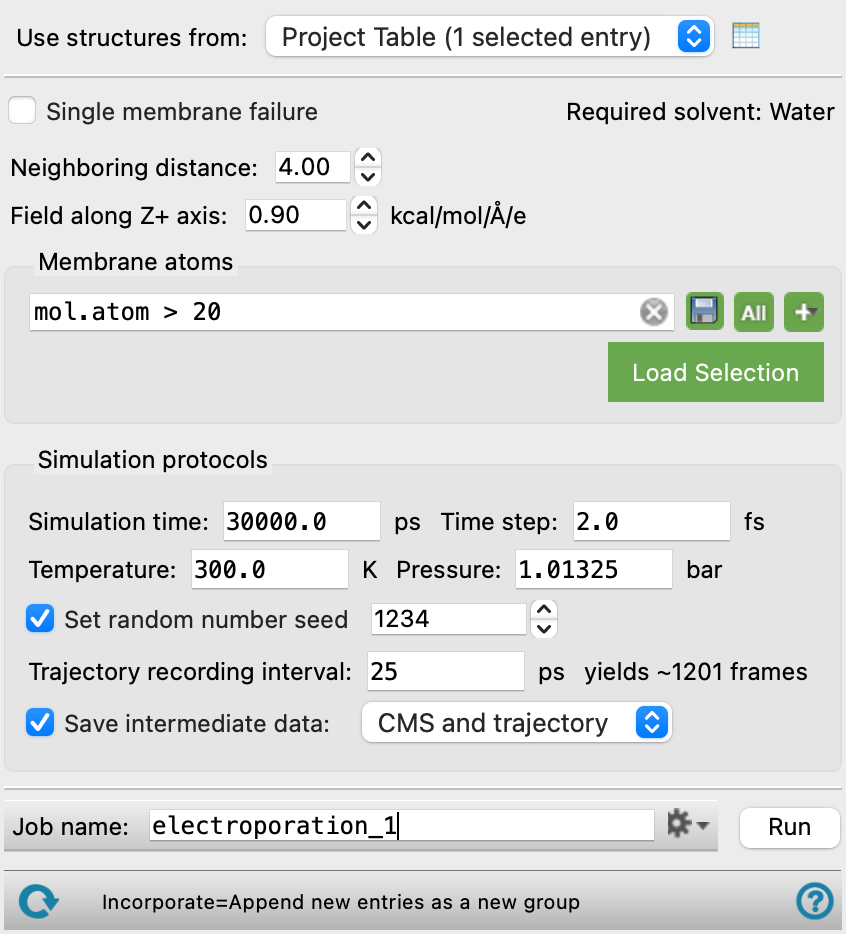
This panel allows you to apply an electric field to a membrane system, which disrupts the membrane and causes pore formation. The likelihood of pore formation is plotted as part of the calculation, and can be used to assess the stability of a membrane.
The input structure format should be a Desmond model system (CMS file) consisting of one or more membranes surrounded on the top and bottom by water molecules. You can build such a system using the Build Structured Liquid Panel. It is recommended you include several (20-25) replicates of the system as part of the input, as the probability of pore formation can be better represented if multiple replicates are used. Replicates can be distributed across GPUs (in the Job Settings Dialog Box), one for each replicate.
An electric field with a user-specified strength is applied to the system, followed by an MD simulation in the NPT ensemble. Pores are created when water molecules penetrate the membrane and come within a user-specified distance of one another. The formation of a pore in a membrane is also referred to as membrane failure. After the calculation is complete, you can load the output into Maestro. The structures incorporated in the Workspace show the point at which a pore has formed. The simulation time at the point is recorded for each replicate. Use the Workflow Action Menu  to display a plot of this data (blue line). The plot shows pore formation probability (Probability no pore forms) vs simulation time in nanoseconds (Time). With every pore formation that occurs in a replicate, the probability that no pore forms in the system decreases. In other words, the probability that a pore forms in the system increases. A fitted orange line is also displayed.
You can manually inspect a trajectory at the time that a pore formation is recorded to assess if the calculation has correctly determined when the formation has happened. To return trajectory files, select CMS and trajectory from the Save intermediate data option menu.
To write out the input file and a script for running the job from the command line, click the arrow next to the Settings button  and choose Write.
Electroporation Calculation Panel Features
- Use structures from option menu
-
Choose the structure source for the electroporation simulation.
- Project Table (n selected entries)—Use the entries that are currently selected in the Project Table or Entry List. The number of entries selected is shown on the menu item.
- Project Table (n selected entries)—Use the entries that are currently selected in the Project Table or Entry List. The number of entries selected is shown on the menu item.
- Open Project Table button
-
Open the Project Table panel, so you can

- Single membrane failure option
-
This option determines what is considered membrane failure in a system that contains more than one membrane. If selected, the simulation time at which the first pore is formed in a membrane is recorded as the time of pore formation. If not selected, the simulation time at which pores have formed in all membranes in the system is recorded as the time of pore formation.
- Required solvent text
-
The solvent in the system must be water molecules.
- Neighboring distance text box
-
Pore formation occurs when water molecules penetrate the membrane and get within the Neighboring distance of one another. The value in this text box determines what is considered a pore. To define a stricter criteria for what is considered a pore, set a smaller Neighboring distance. The default is 4.0 Å.
- Field along Z+ axis text box
-
Specify the electric field that is applied to the system. A positive value applies the field from the positive Z direction while a negative value applies the field from the negative Z direction. A higher electric field is more disruptive to the membrane and therefore causes pores to form sooner in the simulation.
- Membrane atoms section
-
Select all atoms which are part of the membrane. All molecules which are not the water solvent should be included. This section contains a standard set of picking tools that you can use to select atoms.
- Simulation Protocol section
-
Specify options for the MD simulation, which is run in the NPT ensemble.
- Simulation time text box
-
Specify the desired simulation time in ps.
- Time step text box
-
Specify the time step for the simulation in fs.
- Temperature text box
-
Specify the temperature to be used, in kelvin.
- Pressure text box
-
Specify the pressure to be used, in bar.
- Set random number seed option and text box
-
Select this option to specify a random seed to be used in the simulations. Specifying the seed allows you to reproduce the results, unless other factors affect them. If this option is not selected, a seed is chosen at random.
- Trajectory recording interval text box
-
Set the recording interval for saving points on the trajectory, in ps. This is the amount of time between frames in the trajectory. The entered value is rounded to an integer multiple of the far time step size. The resultant number of records to be written is reported to the right.
- Save intermediate data option and menu
-
Select this option to save data from the Desmond MD simulations. The menu has two choices:
- CMS files—save the CMS files from each of the Desmond simulations. These are the files that contain the structure and force field information.
- CMS and trajectory—save the CMS files and the trajectories from each of the Desmond simulations. Note that trajectory files can be large and may take up a lot of disk space.
- Job toolbar
-
Manage job submission and settings. See Job Toolbar for a description of this toolbar.
The Job Settings button opens the Electroporation Calculation - Job Settings Dialog Box, where you can make settings for running the job.
- Status bar
-
 to reset the panel to its default settings and clear any data from the panel.
If you can submit a job from the panel, the status bar displays information about the current job settings and status for the panel. The settings include the job name, task name and task settings (if any), number of subjobs (if any) and the host name and job incorporation setting. The job status can include messages about job start, job completion and incorporation.
The status bar also contains the Help button
 , which opens an option menu with choices to open the help topic for the panel (Documentation), launch Maestro Assistant, or if available, choose from an option menu of Tutorials. If the panel is used by one or more tutorials, hover over the Tutorials option to display a list of tutorials. Choosing a tutorial opens the tutorial topic.