Build Structured Liquid Panel
Build surfactant systems such as micelles, liposomes and bilayers from multiple surfactant molecules and solvent molecules.
To open this panel: click the Tasks button and browse to Materials → Structure Builders → Structured Liquid.
The following licenses are required to use this panel: MS Maestro, MS CG (optional), OPLS (optional), MS Force Field Applications (optional)
- Using
- Features
- Additional Resources
Using the Build Structured Liquid Panel
This panel is used to build an orthorhombic cell that contains a micelle, liposome, monolayer, or bilayer immersed in a solvent. These structures can consist of multiple layers, in which bilayers are added to the fundamental unit (simple micelle, liposome, monolayer, or bilayer). Each layer can consist of a mixture of surfactant molecules, and the solvent can likewise consist of a mixture of solvent molecules.
The molecules used can be either all-atom or coarse-grained; you cannot include both types in the same system.
The building is done with the PackMol program, which uses PDB file format for input and output. This requires certain PDB properties to be assigned to the input structures. If you do not assign these properties, an automatic assignment is done when you click Run, on response to a prompt. You might (for example) want to assign the head (hydrophilic group) as one residue, the end of the hydrophobic tail as another, and the rest as a third, so you can use the residue properties to control the display of these parts of the surfactant in the output structure.
To assign the PDB properties, you can use the 3D Builder, as follows:
-
Open the 3D Builder panel by clicking the Build button in the main window.

-
Display a component molecule in the Workspace.
-
Select the atoms you want to include in the first residue.
-
In the 3D Builder panel , choose Other Edits → Change Atom Properties.
You must have an atom selection to do this. The Change Atom Properties Panel opens.
-
Set Property to PDB Atom Name.
-
Select Set unique PDB atom names within residues.
This action will be applied along with the other changes that you make below.
-
Set Propertyto Residue / Chain Name.
-
Check the Residue Name check box, and enter a name in the text box.
The residue name can be 4 characters long, and must be unique within a chain, but you can use the same name in different components for the same residue.
-
Check the Chain Name check box, and enter a single-letter name in the text box.
The chain name must be the same for all residues in a component, and must be different for each component.
-
Check the Residue Numbers check box, select Apply residue number, and enter a number in the New number text box.
The number must be unique within a chain.
-
Click Apply.
-
Select the atoms for the next residue in the Workspace, enter the residue name and number in the panel, and click Apply. Repeat for all residues in the molecule.
-
Display the next component in the Workspace and select atoms for the first residue.
-
Change the chain name, enter the residue name and number, and click Apply.
-
Repeat step 12 for all the residues in this component.
-
Repeat from step 13 for each component.
-
Close the Change Atom Properties Panel.
Please cite the PackMol references [27, 28] in any publication that contains results from the use of this panel.
Once you have built a model system, you may want to equilibrate it, using the Molecular Dynamics Panel, or run a series of MD steps with the MD Multistage Workflow Panel.
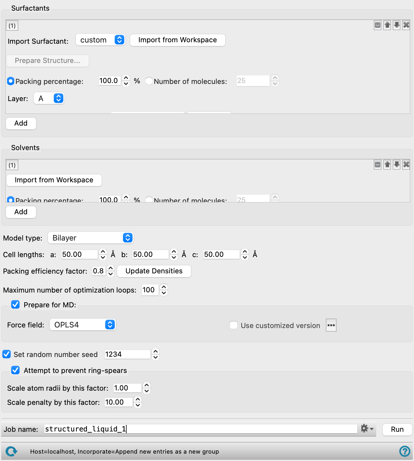
Build Structured Liquid Panel Features
- Common tool set features
- Surfactants section
- Surfactant tools
- Add button
- Solvents section
- Model type option menu
- Outer radius text box
- Elongation scale factor text box
- Cell lengths text boxes
- Packing efficiency factor text box
- Update Densities button
- Maximum number of optimization loops text box
- Prepare for MD option
- Set random number seed option and text box
- Attempt to prevent ring-spears option and section
- Job toolbar
- Status bar
- Common tool set features
-
Several features are common to the tool sets for adding surfactants and adding solvents. These are listed below.
- tool set management buttons
-
These buttons perform display and ordering operations on the tool set. They allow for easy duplication and rearrangement of tool sets.


Show or hide the contents of the tool set. When hidden, only the tool set number, label (if any) and these buttons are displayed. This is useful when you have a number of tool sets and want to compare two separate tool sets, for example. 
Delete the tool set. - Import from Workspace button
-
Use the structure from the Workspace for the current component. The structure is copied into the workflow, to be added to the output structure. The Workspace must contain a single molecule.
- Packing percentage option and text box
-
Specify the packing percentage for this component. The packing percentages must add up to 100% for each layer if all components are specified by a packing percentage. The packing efficiency is applied to this component to control the density. This is the recommended way of specifying the component amounts.
- Number of molecules option and text box
-
Specify the number of molecules to add for this component. The packing efficiency is ignored for this component.
- Surfactants section
-
Define the surfactants using the tools in this section. Each surfactant is specified with one set of tools. A set of tools can be added with the Add button.
An arrow from the hydrophilic to hydrophobic group is displayed in the Workspace for each surfactant.
For ionic surfactants, you can add the counter ions to the solvent.
- Surfactant tools
-
Each set of surfactant tools has the following features in addition to the common features:
- Import Surfactant option menu
-
Select to import a custom lipid or select a predefined membrane lipid molecule to import as a surfactant from the option menu. ADPG, ALPG, AMPG, DMPC, DOPC, DPPC, POPC, and POPE lipids are available. The force field parameters for these predefined lipid molecules are optimized to reproduce bulk properties of a pure bilayer. Click Import to Workspace to import the selected predefined lipid. Click Import from Workspace to use the structure from the Workspace for the custom lipid.
- Import to Workspace button
-
Click Import to Workspace to import the selected lipid. After successful import, a message is displayed next to the Import to Workspace button.
- Prepare Structure button
-
Click to open the Prepare Structure Menu to set additional options for the custom lipid. The structure name is displayed next to the Prepare Structure button. Only available when the Import Surfactant option menu is set to custom.
- Set double bond stereochemistry option
-
Choose to set the stereochemistry for double bonds in the custom lipid. The choices are Cis and Trans.
- Set chiral center stereochemistry option
-
Choose to set the stereochemistry for chiral centers in the custom lipid. The choices are R and S.
- Generate optimized conformation option
-
Choose to generate multiple conformations of the custom lipid. The structure with the head and tail atoms the furthest distance away from each other is used for the system building. Only available when the Set double bond stereochemistry option and Set chiral center stereochemistry option are not selected.
- Renumber phospholipid tails option
-
Choose to renumber the phospholipid tails in the custom lipid.
- Prepare button
-
Click to prepare the custom lipid based on the parameters selected here.
- Cancel button
-
Click to exit the menu without preparing the custom lipid and return to the panel.
- Layer option menu
-
Specify the layer that this surfactant is to be added to. You can include multiple surfactant molecules in a layer, in proportions given by the packing percentage. Layers are added to the surfactant structure in alphabetical order of layer letter.
- Hydrophilic end atom indices text box and Define button
-
Enter the indices of the atoms in the hydrophilic end of the surfactant. Click Define to open the Atom Selection Dialog Box to select the atoms. You can show the atom numbers (indices) in the Workspace by selecting Apply Labels → Element + Atom Number in the Style toolbox.
The Hydrophilic end atom indices are automatically populated if a predefined membrane lipid molecule is used from the Import Surfactant button and option menu. The indicies are also be automatically populated for certain custom lipid molecules.
The atoms specified here are constrained to a particular region of space when the molecule is placed in the chosen surfactant structure. The atoms do not need to be bonded to each other. If the structure has multiple hydrophilic head groups (such as in a hairpin structure), you should select atoms from all of them, so that they are all confined to the hydrophilic region of the surfactant structure. You should include terminal atoms, such as hydrogen.
- Hydrophobic end atom indices text box and Define button
-
Enter the indices of the atoms in the hydrophobic end of the surfactant. Click Define to open the Atom Selection Dialog Box to select the atoms. You can show the atom numbers (indices) in the Workspace by selecting Apply Labels → Element + Atom Number in the Style toolbox.
The Hydrophilic end atom indices are automatically populated if a predefined membrane lipid molecule is used from the Import Surfactant button and option menu. The indicies are also be automatically populated for certain custom lipid molecules.
The atoms specified here are constrained to a particular region of space when the molecule is placed in the chosen surfactant structure. The atoms do not need to be bonded to each other. If the structure has multiple hydrophobic tail groups (such as in a hairpin structure), you should select atoms from the ends of all of the tails. This ensures that they are all confined to the outer side of the hydrophobic region. You should include terminal atoms, such as hydrogen.
- Include counter ion option and Import from Workspace button
-
For an ionic surfactant, include a counter ion in the model. Place the counter ion in the Workspace, and click the adjacent Import from Workspace button to add the counter ion to the model. The counter ion must have the opposite charge to the surfactant molecule, to ensure that the system is neutral.
This option is only present if the loaded surfactant molecule is ionic. If it is not selected, the structure is built without the counter ion. You can add counter ions by using the Disordered System Builder Panel with the surfactant structure as an immersed substrate.
- Add button
-
Add a set of surfactant tools for a new surfactant. The new tools are placed at the bottom of the list.
- Solvents section
-
Define the solvents using the tools in this section. You can specify multiple solvent molecules to create a mixed solvent, in proportions given by the packing percentage. For a monolayer, you must specify a solvent for each side (hydrophobic and hydrophilic). For bilayers and other model types, the same mixture is used on all sides of the model. If you have ionic surfactants, you can add the counter ions as solvent molecules, to create an overall neutral system.
- Model type option menu
-
Choose the type of structured liquid to build:
-
Monolayer—build a monolayer from the surfactant, with a polar solvent on the hydrophilic side and a nonpolar solvent on the hydrophobic side. This can be used to create a surfactant monolayer at an oil/water or water/air interface, for example. If you specify multiple layers, bilayers can be added to the hydrophilic side. The layers are oriented perpendicular to the c lattice vector.
When you choose this option, the Layer option menu is added to the solvent tools, so you can specify solvents for the hydrophilic and the hydrophobic side of the layer. This option is intended for use to build another system for MD simulations: using the built cell directly for MD would result in an interface between the polar and nonpolar solvents at the cell boundary.
-
Bilayer—build a single bilayer or a stack of bilayers. The solvent is added on either side of the stack. The layers are oriented perpendicular to the c lattice vector. The total number of molecules in the cell is 2 x Number of molecules x N, where N is the number of bilayers in the stack.
-
Micelle—build a micelle (spherical monolayer with no cavity) from the surfactant molecules. The micelle can consist of an inner spherical monolayer, with bilayers added successively to the exterior.
-
Liposome—build a liposome (spherical bilayer with a cavity) from the surfactant molecules. The liposome can have bilayers added successively to the exterior. You can specify the radius of the outermost bilayer, and the size of the cavity is determined by this radius and the number of layers. Solvent molecules are added inside the cavity.
When you choose this option, the Outer radius text box is displayed, so you can specify the outside radius of the outermost bilayer.
-
Wormlike Micelle—build a tubular micelle, with the tube oriented along the c lattice vector. The micelle can consist of an inner tubular monolayer, with bilayers added successively to the exterior.
-
Elongated Micelle—build an ellipsoidal (prolate) micelle. The micelle can consist of an inner spherical monolayer, with bilayers added successively to the exterior.
When you choose this option, the Elongation scale factor text box is displayed, so you can specify the shape of the ellipsoid.
-
- Outer radius text box
-
Specify the outer radius of the liposome. This is the radius of the outermost bilayer, which is in contact with the solvent. The inner radius is determined by this radius and the number of bilayers used to build the liposome. Only present when the Model type is set to Liposome.
- Elongation scale factor text box
-
Specify the elongation factor for an elongated micelle. This is the ratio of the long axis to the short axis of the ellipsoid.
- Cell lengths text boxes
-
Set the a, b, and c cell lengths (in angstroms) for the resultant orthorhombic periodic system. The default values of these lengths are adjusted as settings are made to define the surfactant structure. If you set them manually, you should ensure that they are large enough to allow a sufficiently large solvent buffer between the surfactant structure and the cell boundary. For MD simulations, a 10 Å solvent buffer is typically used for solute molecules in solution.
- Packing efficiency factor text box
-
Specify the relative packing efficiency, on a scale of 0 to 1, where 1 means the tightest packing possible, and 0 means the loosest packing. This factor is related to the density of the system. You may need to lower the packing efficiency if the job fails to place all the molecules.
This option only applies to component compositions specified by percentage, and is not available if the compositions of the layers are all specified by number.
- Update Densities button
-
Update the partial and total densities calculated from the settings in the panel. The partial densities are reported to the right of the Number of molecules text box for each surfactant and solvent molecule, and the total density is reported to the right of this button. Changing the settings clears the density values. These values can be used to check that the cell is not over-packed.
- Maximum number of optimization loops text box
-
Specify the maximum number of optimization loops to use in the packing process to improve the positions of the molecules (PackMol
nloopsetting). A suggested smallest value for this parameter is 40. Further refinement can be done in the MD equilibration and simulations. - Prepare for MD option
-
Select this option to create a Desmond model system (CMS file) for MD simulation. The default is to simply create a periodic system. The model system requires the specification of the force field. The tools available for specifying the force field depend on whether you have an all-atom or a coarse-grained system.
For all-atom systems, the following tools are available:
- Force field option menu
-
Choose the force field for the MD simulations.
- Use customized version option
-
Use your customized version of the OPLS4 or OPLS5 force field, rather than the standard version in the distribution.
If the customized version is missing or invalid, the text of this option turns orange and an orange warning icon is displayed to the right, with a tooltip about the problem.
- Parameter set button
-
Select the set of custom parameters for the OPLS4 or OPLS5 force field. Opens the Set Custom Parameters Location Dialog Box.
- Water model option menu
-
If water is one of the components of the system, choose the water model for the simulations. The water models available on the menu depend on the force field. For OPLS4, the models are SPC, SPCE, TIP3P, TIP4P, TIP4P2005, TIP4PEW, TIP5P, TIP4PD. For OPLS_2005, only the SPC and TIP3P models are available. If the water model is already assigned, choose Current to retain this model.
-
This option menu is only available if you import water as a solvent molecule.
For coarse-grained systems, the following tools are available:
- Coarse-grained force field option menu
-
Choose the coarse-grained force field for the MD simulations. The choices depend on the Location option selected. The installation contains the Martini and Martini_solution force fields. The menu is populated with the coarse-grained force fields you have saved if you choose Local for the Location.
- Description button
-
Display a description of the chosen force field in a separate panel.
- Location options
-
Select an option for the location of the coarse-grained force field. The force fields listed on the Force field option menu depend on this choice.
- Installation—use the force fields in the installation. These are the Martini, Martini_solvation, or Martini_full force fields [15].
- Local—import a force field from your local user resources directory. These are force fields that you have saved for your own use.
- Set random number seed option and text box
-
Select this option to specify a random seed to be used in various random operations, such as selection of components and placement location. Specifying the seed allows you to reproduce the results, unless other factors affect them. If this option is not selected, a seed is chosen at random.
- Attempt to prevent ring-spears option and section
-
Select this option to attempt to prevent the formation of ring-spears in the structured liquid. This is attempted by placing a dummy atom in the center of rings and calculating the radius between the ring atoms and the dummy atom. The Scale atom radii by this factor and Scale penalty factor by this factor parameters are used to avoid close contacts involving the rings during system packing. Non-ring atoms are allowed to be in closer contact to ensure the system is built to the proper density.
If ring-spears are still present the job will fail, but the outputs will be returned.
This option is selected by default.
- Scale atom radii by this factor text box
-
Specify the factor to scale the dummy atom to ring atoms radius by. Note that using too large of a value for this parameter can greatly increase calculation time.
Only available if Attempt to prevent ring-spears is selected.
- Scale penalty factor by this factor text box
-
Specify the factor to scale the weight of the dummy atom to ring atoms distance penalty function by.
Only available if Attempt to prevent ring-spears is selected.
- Job toolbar
-
Manage job submission and settings. See Job Toolbar for a description of this toolbar.
The Job Settings button opens the Build Structured Liquid - Job Settings Dialog Box, where you can make settings for running the job.
- Status bar
-
The status bar displays information about the current job settings and status for the panel. The settings includes the job name, task name and task settings (if any), number of subjobs (if any) and the host name and job incorporation setting. The job status can include messages about job start, job completion and incorporation.
Use the Reset button
 to reset the panel to its default settings and clear any data from the panel.
 The status bar also contains the Help button
 , which opens the help topic for the panel in your browser. If the panel is used by one or more tutorials, hovering over the Help button displays a
  button, which you can click to display a list of tutorials (or you can right-click the Help button instead). Choosing a tutorial opens the tutorial topic.