New Crystal Structure Panel
Build a crystal structure entirely from text data, such as data found in a publication, or from a 3D structure and information on the unit cell. The crystal structure is stored as a project entry with crystal properties.
To open this panel: click the Tasks button and browse to Materials → Structure Builders → Crystal Structure.
The following licenses are required to use this panel: MS Maestro
- Using
- Features
- Additional Resources
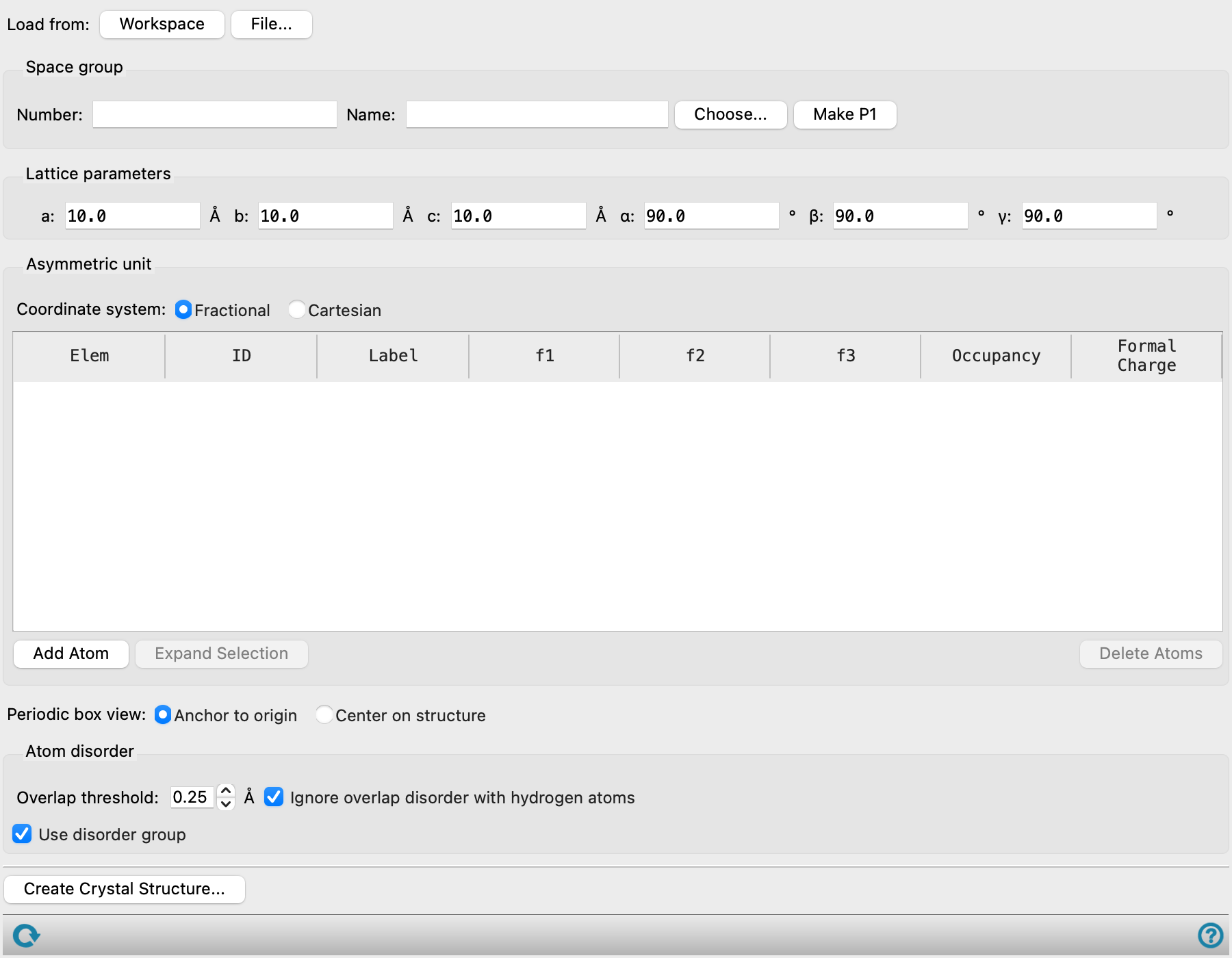
Using the New Crystal Structure Panel
To create a crystal structure from text data:
-
Enter the space group number, type in the name, or click Choose to choose the space group.
The Select Space Group dialog box, which opens when you click Choose, allows you to filter the list of space groups by the crystal system and by the lattice type. Similarly, a list of space group names is shown below the text box if you type in the space group name, and it is filtered as you type. You can choose the space group name from this list.
The space group number and name are filled in. The text boxes for the parameters are updated so that only the unique parameters can be specified.
-
Enter the lattice parameters in the available text boxes.
The remaining parameters are set from the unique parameters.
-
Choose a coordinate system to use. Fractional coordinates are recommended for single crystals, while Cartesian coordinates are recommended for larger systems such as polymers and large MD boxes.
-
Click Add Atom to add an atom to the asymmetric unit.
A new atom is added to the table with fractional coordinates of (0, 0, 0).
-
Change the element by clicking on the element button and choosing the element from the periodic table that is displayed.
-
If Fractional coordinates are selected, enter the fractional coordinates of the atom in the f1, f2, and f3 columns. The fractional coordinates must be in the range [−0.5, 0.5] or [0.0, 1.0]. The range used determines the origin of the unit cell. If Cartesian coordinates are selected, enter the Cartesian coordinates of the atom in the c1, c2, and c3 columns (in units of angstroms).
-
(Optional) Change the ID for the atom.
The default ID is the element symbol followed by an index that indexes atoms for each element. It is updated if you change the element. Once edited, the custom ID is kept.
-
Repeat the above four steps for each atom in the asymmetric unit.
-
Click Create Crystal Structure, and provide a title for the structure in the dialog box that opens.
To create a crystal structure from a 3D structure that has no crystallographic information:
-
Click one of the Load from buttons to add the atoms from the 3D structure to the asymmetric unit: Workspace, if the structure is in the Workspace, or File, to read a structure from a Maestro file.
The unit cell is built with P 1 symmetry, and the parameters are assigned automatically.
-
(Optional) Change data for any of the atoms.
-
Click Create Crystal Structure, and provide a title for the structure in the dialog box that opens.
To create a new crystal structure from a 3D structure that already has crystallographic information:
-
Click one of the Load from buttons to load the crystallographic information and add the atoms from the 3D structure to the asymmetric unit: Workspace, if the structure is in the Workspace, or File, to read a structure from a Maestro, PDB, or CIF file.
-
(Optional) Change data for any of the atoms.
-
Click Create Crystal Structure, and provide a title for the structure in the dialog box that opens.
To convert a structure to P 1 symmetry:
-
Click Make P1.
The structure is converted to P 1 symmetry by applying the symmetry operations of the current space group, and the Atoms table is populated with the symmetry-degenerate atoms.
-
Click Create Crystal Structure, and provide a title for the structure in the dialog box that opens.
The new structure is an entry in the Project Table, which can be exported into a variety of file formats that are designed for crystal structures. If you want to redefine the lattice parameters, you can use the Redefine Lattice Panel. The Hermann-Mauguin (international) notation is used for the space group. The space group and Z value are stored as properties in the new project entry.
New Crystal Structure Panel Features
- Load from buttons
-
If you want to use an existing 3D structure, you can load it from a file or from the Workspace. The file can be in Maestro, PDB, or CIF format. The Atoms table is populated with the structure data.
If the structure has crystallographic data associated with it (space group and cell parameters), these values are used to set the space group and parameters. If the structure does not have crystallographic data, it is assigned P 1 symmetry and the parameters are set automatically. The space group cannot be subsequently changed, except to generate a structure in P 1 symmetry.
- Space group section
-
In this section you define the space group, by number, name, or choice from a list.
If you read the asymmetric unit from a file or the Workspace, and crystallographic information is stored with the structure, the space group is set from this information, and cannot be changed except by converting to P 1.
When the space group is chosen, the availability of and values in the Lattice parameters text boxes are changed to match the restrictions in the space group (e.g. all angles are 90° and cannot be changed).
- Number text box
-
You can enter the space group number in this text box. The space group name is added to the second text box.
- Name text box
-
You can enter the space group name in this text box. As you type in the name, a completion list is displayed below the box that is updated as you type, and you can choose the name from this list. The space group number is shown in the Number text box.
- Choose button
-
Click this button to choose the space group in the Select Space Group dialog box.
- Make P1 button
-
Click this button to convert a structure from a higher symmetry to a structure in P 1 symmetry. The non-symmetry-unique atoms are added to the Atoms table, and the space group is set to P 1. After you do this you can no longer change the space group, but you can still change the parameters.
- Lattice parameters section
-
Specify the lattice parameters a, b, c, in angstroms and α, β, γ, in degrees. Only the values that are not restricted by the space group can be changed; the others are set according to the space group.
If you read in a file that already has crystallographic information, the cell parameters are set from the values in the file and cannot be changed.
- Asymmetric unit section
-
In this section you specify the atoms in the asymmetric unit.
- Coordinate system options
-
Choose the type of coordinates to use.
- Fractional—Use fractional coordinates. The fractional coordinates must be in the range [−0.5, 0.5] or [0.0, 1.0]. The range used determines the origin of the unit cell. If this option is selected, the Atoms table has column headers f1, f2, and f3.
- Cartesian—Use Cartesian coordinates (in angstroms). If this option is selected, the Atoms table has column headers c1, c2, and c3.
- Atoms table
-
This table lists the atoms in the asymmetric unit, giving the element, an ID (which need not be unique), the fractional or cartesian coordinates of the atom, the occupancy, and the formal charge. The table columns can be sorted by clicking on the column heading. The ID column is sorted by the numerical index, not the entire string. Selecting rows in the table selects the corresponding atoms in the Workspace structure (and deselects any others). Likewise, selecting atoms in the Workspace selects the corresponding table rows and deselects any others.
The element symbol is shown on a button, which you can use to change the element. Clicking the button opens the Choose Element dialog box, which displays a periodic table. To set the element, double-click it or select it and click OK. Once set, it is used as the default element for adding new atoms. The ID is updated to use the new element, if it has not already been manually set (see below).
The ID column is used to identify the particular atom in the asymmetric unit. The default for this column is the element symbol followed by an index, which indexes the atoms of the asymmetric unit. You can edit the ID cell to set the ID for a given atom. Once edited, it is no longer updated automatically.
The Label column displays the PDB atom name, or if a structure from a CIF file is loaded, the
_atom_site_labelproperty. This label is used to identify possible multiple instances of molecular disorder in a single CIF file.If Fractional is selected as the coordinate system, coordinate column headers f1, f2, and f3 are shown. The fractional coordinates can be edited, and must be in the range [0,1] or [-0.5, 0.5]. Fractional coordinates are unitless. The range used determines the origin of the unit cell.
If Cartesian is selected as the coordinate system, coordinate column headers c1, c2, and c3 are shown. The Cartesian coordinates can be edited, and are in units of angstroms.
The Formal Charge can be set or edited, and must be an integer value.
The Occupancy can be edited, and must be in the range 0 to 1 inclusive. The occupancies for equivalent sites must sum to 1.
To edit a cell in a selected row, click in the cell. You can also double-click any text cell to edit it, and you can tab between cells to edit them. If you want to apply a value to all selected rows in a given column, press Ctrl+Enter (⌘⏎) after editing the value.
- Add Atom button
-
Add an atom to the asymmetric unit. A row is added to the table, with the default element and ID, default coordinates of (0,0,0), and occupancy of 1.0.
- Expand Selection button
-
Add atoms to the selection that are symmetrically equivalent to the atoms currently selected in the Atoms table. No atoms are added to the selection if there are no symmetry-equivalent atoms or if they are already selected.
This button is only available if one or more entries of the Atoms table are selected.
- Delete button
-
Delete the selected atoms from the asymmetric unit.
- Periodic box view options
-
Select an option for the display of the periodic box in the Workspace. These options apply only to the displayed box, not to the coordinates of the atoms, for which the origin is always (0,0,0).
- Anchor to origin−Place the origin of the box at the coordinate origin.
- Center on structure—Center the box on the atoms in the structure.
- Overlap threshold text box
-
Specify the threshold for detecting atoms that are occupying the same site. When two or more atoms are within this distance of each other, they are considered to occupy the same site. To build a crystal structure, you will have to resolve the overlap by choosing one of the atoms from each set. This is done in the Resolve Disorder Dialog Box.
- Ignore overlap disorder with hydrogen atoms option
-
Select this option to ignore hydrogen atoms that are bonded to heavy atoms when detecting if two atoms occupy the same site.
- Use disorder group option
-
Use a disorder group as defined in the input structure to resolve overlapping atoms. Disorder group information is included with a structure when it is imported from a CIF file. When you click Create Crystal Structure, the Resolve Disorder Dialog Box opens, so you can select the group of atoms to use for resolving the overlaps. Disorder groups can contain multiple atoms so that you only need to select one group to resolve all the overlaps. This is in contrast to the use of the overlap threshold, where each atom overlap must be resolved separately. The overlap threshold is ignored if this option is selected.
- Create Crystal Structure button
-
Click this button to create the crystal structure as a project entry. A dialog box opens in which you can provide the entry title. When the structure is created, it is selected in the Project Table (deselecting all other entries) and the structure replaces the Workspace contents. The space group for the crystal structure is assigned using the Hermann-Mauguin (international) notation. A preference can be set for considering or ignoring atomic valence when the connectivity is calculated, in the Materials Science settings section of the Preferences Panel.
If the structure has atoms that occupy the same site to within an overlap threshold, a warning is posted, and you can choose the atom to use for each site in the Resolve Disorder Dialog Box.
- Status bar
-
 to reset the panel to its default settings and clear any data from the panel.
If you can submit a job from the panel, the status bar displays information about the current job settings and status for the panel. The settings include the job name, task name and task settings (if any), number of subjobs (if any) and the host name and job incorporation setting. The job status can include messages about job start, job completion and incorporation.
The status bar also contains the Help button
 , which opens an option menu with choices to open the help topic for the panel (Documentation), launch Maestro Assistant, or if available, choose from an option menu of Tutorials. If the panel is used by one or more tutorials, hover over the Tutorials option to display a list of tutorials. Choosing a tutorial opens the tutorial topic.