Build Slabs and Interfaces Panel
Build a slab of a specified thickness by slicing a crystal structure along a specified plane, and optionally add a second slab above or below the first, taken from another crystal structure.
To open this panel, click the Tasks button and browse to Materials → Structure Builders → Slabs and Interfaces.
The following licenses are required to use this panel: MS Maestro
- Using
- Features
- Additional Resources
Using the Build Slabs and Interfaces Panel
This panel enables you to generate a new periodic system that is composed of slabs of other periodic systems. The new system can be composed of a slab of one system, sliced along a particular plane and with a specified thickness, with an optional vacuum layer above it (for simulating surfaces in vacuo). It may also contain a slab of another system, with optional vacuum layers between the two different slabs. The second slab (the "epitaxial" layer) is stretched or contracted if necessary so that its lattice constants match those of the first slab. The matching is done on multiples of the lattice constants of each slab, so that the amount of stretching or contraction is small.
If the source structure is a molecular crystal, molecules that span the two planes that define the slab are included in the slab. The atoms in a molecule that spans a plane are considered to be in the vacuum layer. For other structures, the partitioning is done on an atomic basis: atoms that are on or between the two planes that define the slab are included in the slab. Any terminating groups added to satisfy valences at the surface are considered to be in the vacuum layer.
If you simply want to add a vacuum layer to an existing crystal structure, you can use the Redefine Lattice Panel. You can also import predefined and equilibrated slabs using the Import Slabs Panel.
The Workflow Action Menu  for the resulting project entry allows you to open the Disordered System Builder Panel or the Molecular Deposition Panel, as possible places for using the slab or interface.
To define a slab composed of a single layer:
-
Display the source structure in the Workspace.
-
In the Base layer section, click Load.
-
Select Define slab.
-
Specify the Miller indices that define the surface of the slab you want to build.
It might be useful to display the planes in the Workspace, on the structure. To do this, you can use the Show Planes button. You might have to extend the crystal to obtain a reasonable view of the planes, which you can also do from the Build Cell toolbox (see Workspace Tools for Periodic Structures).
-
Specify the distance perpendicular to the plane at which the bottom of the slab starts.
The slice defining the bottom of the slab is made parallel to the defined plane at the specified distance.
-
Specify the thickness of the slab.
-
(Optional) If you want space between this instance of the slab in the periodic structure and the next instance, specify the amount of space in the Vacuum buffer box.
A large distance allows you to simulate a surface in a vacuum (essentially a 2D-periodic structure).
-
(Optional) If the structure is not a molecular solid, you can choose a fragment to terminate any dangling bonds on the surface.
-
Name the job and click Run to run it, or click the Settings (gear) button to make job settings and run the job.
To define a slab composed of two layers:
-
Complete the steps above to define the base layer, but do not run the job.
-
Select Epitaxial layer.
-
Display the structure for the epitaxial layer in the Workspace.
-
Click Load in the Epitaxial layer section.
-
Define the slab, using steps 3 – 8 above.
-
In the Interface section, select an option for the bottom layer of the new system.
You can choose either layer, depending on which faces of the slabs you want to be next to each other.
-
Set the inter-layer separation.
The separation is measured from the top of the vacuum buffer, if you defined one. You can make this separation negative to move the top layer down into the vacuum buffer (or you can decrease or remove the vacuum buffer).
-
(Optional) Translate the top layer along the new lattice vectors by a specified amount in angstroms.
This may be useful to get better alignment of atoms at the interface.
-
(Optional) Change the tolerances for stretching or contracting the epitaxial layer to match the base layer lattice constants, and the maximum number of cell extents permitted to do the matching.
-
Name the job and click Run to run it, or click the Settings (gear) button to make job settings and run the job.
Build Slabs and Interfaces Panel Features
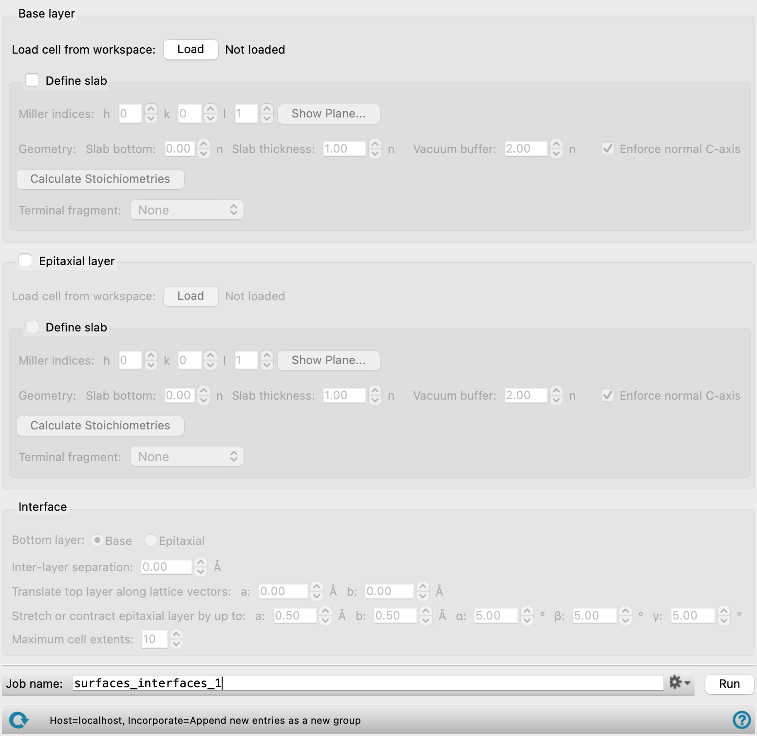
- Base layer section
-
Define the slab for the base layer in this section. For a single slab, you need only define the base layer. For a interfacial (two-layer) system, the base layer is the one onto which the epitaxial layer is added. The base layer maintains its geometry, whereas the epitaxial layer can have a strained geometry.
- Epitaxial layer option and section
-
Define the slab for the epitaxial layer in this section. The epitaxial layer is added to the base layer, and can have a strained geometry, specified in the Interface section.
- Load cell from Workspace button
-
Click the Load button to load a crystal structure (asymmetric unit) from the Workspace as the source for a particular layer. There is an instance of this button in the Base layer section and the Epitaxial layer section.
- Define slab option and section
-
Select this option to define the slab for a particular layer, and enter the information needed to define the slab. There is an instance of this option and section in the Base layer section and the Epitaxial layer section.
- Miller indices settings
-
Specify the Miller indices that define the plane used to slice the crystal to generate the slab.
It might be useful to display the planes in the Workspace, on the structure. To do this, you can use the Show Planes button. You might have to extend the crystal to obtain a reasonable view of the planes, which you can also do from the Periodicity toolbox (see Workspace Tools for Periodic Structures).
- h, k, l boxes
-
Set the Miller indices by entering the values for each index in the boxes.
Note that the (h k l) plane is relative to the lattice vectors of the input cell, which may be different from the lattice vectors of the conventional unit cell of the crystal. You can use the Show Planes button to confirm which plane is being chosen.
- Show Planes button
-
Show the planes at the top and bottom of the slab for the current layer in the Workspace. Opens the Crystal Plane panel, in which you can set some display options. The values of h, k, and l are synchronized with the values in the main panel, and cannot be changed in the Crystal Plane panel. The planes are shown for the layer that is in the Workspace (base or epitaxial).
- Geometry settings
-
These settings define the details of the two slab surfaces and the space above the surface (if any) that defines the new structure. The thickness is given in terms of the number of cells, measured along the c vector. The corresponding thicknesses in angstroms are shown next to the text boxes, followed by the total thickness of the layer.
- Slab bottom box
-
Specify the distance along the normal to the chosen plane (defined by the Miller indices) at which the bottom surface of the slab starts, given in terms of the number of cells. The distance is taken normal to the plane.
- Slab thickness box
-
Specify the thickness of the slab, in terms of the number of cells. The distance is taken normal to the slab bottom plane.
- Vacuum buffer box
-
Specify the amount of empty space (measured normal to the surface) to leave above the top surface of the slab in the new periodic system, in terms of the number of cells.
- Enforce normal C-axis option
-
Force the c axis in the new unit cell to be normal to the a-b plane. This option is on by default. You might want to turn it off to retain the nonorthogonality of axes from the original crystal—for example, so that reducing the vacuum buffer to zero reproduces the original crystal structure.
- Calculate Stoichiometries button
-
Calculate the stoichiometries of the bulk material and the slab being defined, and report the stoichiometries next to the button. This allows you to check whether the slab is stoichiometric or not (i.e. a multiple of a unit cell). The slab stoichiometry is removed from the display when you change the Miller indices or the slab thickness. Click the button again to recalculate the stoichiometry of the new slab. (The calculation takes a little time, so it is not recalculated automatically.)
- Terminal fragment option menu
-
Choose a fragment to terminate any dangling bonds at the top and the bottom of the slab. The same fragment is used to terminate all dangling bonds.
If the dangling bonds are from atoms of different elements, a single fragment might not be appropriate for termination, and it might be necessary to perform the termination manually or to replace some fragments with other fragments.
- Interface section
-
Specify how the two slabs are placed to create a system with an interface.
- Bottom layer options
-
Specify which layer should be the bottom layer of the interface model. The layers are stacked with their surfaces parallel.
- Inter-layer separation box
-
Specify the separation between the two layers, in angstroms. If a vacuum buffer is defined for the bottom layer, this value can be negative to reduce the gap between the layers.
- Translate top layer along lattice vectors boxes
-
Translate the top layer along the lattice vectors a and b by the amounts specified in the boxes. The translation can be used to get a better match between the two structures.
- Stretch or contract epitaxial layer by up to boxes
-
To create a system that is periodic, the periodicity in the two layers must match or be made to match. This is done by stretching or contracting the epitaxial layer by a small amount, whose limit is specified in these text boxes. For the a and b values, a multiple of the a and b values in each slab is found for which the differences are less than the specified tolerance, i.e.
|ma1 − na2| < da
|jb1 − kb2| < dbFor the angle, |γ1 − γ2| < dγ.
- Maximum cell extents box
-
Place a limit on the number of multiples of a and b that can be used to match the two structures: in terms of the equations above, m, n, j, and k must not be greater than the value specified, otherwise the bilayered system is discarded.
- Job toolbar
-
Manage job submission and settings. See Job Toolbar for a description of this toolbar.
The Job Settings button opens the Build Slabs and Interfaces - Job Settings Dialog Box, where you can make settings for running the job.
- Status bar
-
The status bar displays information about the current job settings and status for the panel. The settings includes the job name, task name and task settings (if any), number of subjobs (if any) and the host name and job incorporation setting. The job status can include messages about job start, job completion and incorporation.
Use the Reset button
 to reset the panel to its default settings and clear any data from the panel.
 The status bar also contains the Help button
 , which opens the help topic for the panel in your browser. If the panel is used by one or more tutorials, hovering over the Help button displays a
  button, which you can click to display a list of tutorials (or you can right-click the Help button instead). Choosing a tutorial opens the tutorial topic.