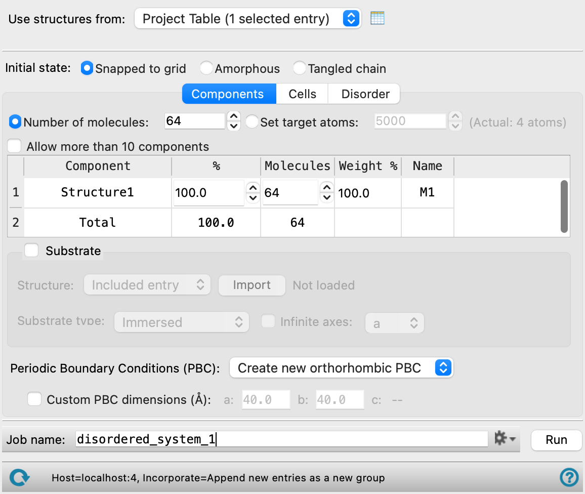
Disordered System Builder Panel
Build a randomized multi-component mixture of a given composition, either on its own, or on a substrate. The substrate can be a solid surface, the exterior of a particle or molecule, or the interior of a structure such as a nanotube or zeolite. The resulting structure can be prepared for molecular dynamics simulations.
To open this panel: click the Tasks button and browse to Materials → Structure Builders → Disordered System.
You can also open this panel with the Workflow Action Menu  in the Entry List (Entries) for the results of a Build Slabs and Interfaces job, as a possible next step.
The following licenses are required to use this panel: MS Maestro, MS CG (optional), OPLS (optional), MacroModel (optional), MS Force Field Applications (optional)
- Using
- Features
- Additional Resources
Using the Disordered System Builder Panel
This panel allows you to create a disordered system from a single compound or a mixture of compounds of a given composition, either on its own, or on a substrate such as a nanoparticle, quantum dot, zeolite, metal-organic framework, or nanotube. Each "compound" corresponds to a single project entry or entry in a file, and can consist of a single molecule (which could be covalently bonded or a metal cluster) or multiple molecules (like a multi-walled nanotube). The system that is constructed can be prepared for Desmond molecular dynamics simulations. If you are preparing a system for coarse-grained modeling, the compounds can also be coarse-grained particles. Here we will refer to them as "structures".
The basic input is a set of structures, which can be a set of entries in the Project Table or in a single file that contains only the desired structures. You choose the proportions of each structure in the mixture, and the total number of structures to place in the simulation box. If you want a pure substance rather than a mixture, you can simply choose a single structure as input. However, you can also choose to build homogeneous cells of each component, in addition to the mixture, in the Cells section.
The proportions or percentages that you specify must be regarded as a target value, as there must be an integer number of structures in the disordered system. The larger the number of structures in the box, the closer the actual proportions will be to the target values. Of course, the resources for the simulation and the display of results in Maestro also increase with the number of atoms in the simulation. For guidance, Maestro can display over 1,000,000 atoms comfortably in the Workspace with modern, quality hardware (and 32GB memory); a Desmond simulation with about 100,000 atoms can run 100 – 200 ns per day on a recent GPU. If you are preparing a simulation box, you should in any case ensure that the box is not too small - each side must be at least 20 Å, which means a minimum of around 3000 atoms.
The cell containing the mixture can be replicated with different random distributions and orientations of the components (but in the same proportions), so that you can check the variation with initial conditions, or accumulate statistics for the system. You can also create cells for each of the pure compounds, and have multiple randomly distributed replicas of these as well.
There are several choices for how the structures are placed in the box. An initial placement is made, which can be followed by up to three stages of modification that can relax the system, pack the system more densely, or minimize its energy.
-
If you choose Snapped to grid, the structures are chosen at random and placed on a cubic grid, optionally with random orientation. The box is filled up in order of increasing values of x, y, then z. If the number of structures is not a perfect cube, there is space remaining at the top of the box, and the box side parameters are adjusted afterward. To ensure that the box does not have empty space that the MD simulations must fill, you should choose the number of structures so that only one or two full layers of structures are missing from the cube (that is, n3−n2 or n3−2n2).
-
If you choose Amorphous for the initial placement, the structures are chosen randomly, placed randomly, and oriented randomly, inside the box. If after a specified number of attempts (set in the Disorder Options dialog box) to create a system without clashes, the density or the van der Waals radii are decreased in order to find a system without clashes. You can request that the density is maximized after finding a system without clashes.
-
If you choose Tangled chain for the initial placement, structures with rotatable bonds are rebuilt inside the box, using a self-avoiding random walk algorithm. The initial fragment for each structure with rotatable bonds is placed randomly, along with any structures that are do not have rotatable bonds. The structures with rotatable bonds are then rebuilt to avoid clashes with other structures. The structures are placed in descending order of length, i.e. largest first. This prevents problems where the smaller molecules are distributed evenly and it is extremely difficult to place the larger molecules.
After the initial placement, you can perform any of the three post-placement processes in the Disorder Options dialog box.
-
The first, Steric pack, attempts to maximize the density of the system by moving structures towards the substrate or the center of the box (if there is no substrate). Packing is done by moving each structure towards the substrate or the origin in a straight line, and the structure is placed in the nearest cavity to the substrate or the origin that has no steric clashes. The process starts with the structures that are closest to the substrate or origin and moves outwards.
-
The second, Monte Carlo simulated annealing, allows you to translate and rotate the structures at random at a set of decreasing temperatures, using either a chosen force field, or an energy term that is linear in the minimum distance between any atom in the structure and any atom in the substrate (or the center of the box, if there is no substrate), or both. The linear term encourages structures to move towards the substrate (or center). The force field encourages structures to move to more energetically favorable locations, while ensuring that clashes do not occur. (If you don't use the force field, clashes are avoided with a hard-sphere model.)
-
The third, Minimization, attempts to minimize the energy of the system using a chosen force field. This is the only option available with Tangled chain initialization.
After these processes have been carried out, the box is refit to the final system, to minimize the empty space, while remaining orthorhombic.
If you select the option to prepare Desmond systems, the output consists of one or more CMS (.cms) files, which you can use directly in Desmond MD simulations. The file containing the model system for the mixture is named jobname.cms, so you should choose a descriptive job name (rather than the default). The files containing the model systems for the components are named jobname-componentn.cms, where n is the component number in the Components table. If you chose to generate multiple cells of each type, a suffix _N is added, where N indexes the replicas of each type.
If you chose not to prepare Desmond systems, the output consists of Maestro files that contain the periodic boundary condition properties, and are named in the same way as the Desmond systems except with the suffix .maegz.
If you are using this panel to build a system for coarse-grained modeling, some of the choices described above do not apply. See Constructing Disordered Systems for Coarse-Grained Modeling for more information.
To write out the input file and a script for running the job from the command line, click the arrow next to the Settings button  and choose Write.
For a tool to create multiple binary disordered systems with a more limited range of options, see the Enumerate Disordered Systems Panel topic.
Disordered System Builder Panel Features
- Structure source
- Initial state options
- Components tab
- Number of molecules option and text box
- Set target atoms option and text box
- Allow more than 10 components option
- Components table
- Substrate option and section
- Structure option menu and button
- Substrate type option menu
- Define interface button
- Infinite axis option and menu
- Periodic boundary conditions option menu
- Custom periodic boundary conditions dimensions option and text boxes
- Cells tab
- All components option
- Homogeneous cell of each component option
- Number of cells of each type box
- Prepare Desmond systems option and Force Field button
- Water model option menu
- Disorder tab
- Color molecules by component option
- Initial VdW scale factor text box
- Initial density text box
- Keep constant options
- Disorder Options button
- Job toolbar
- Status bar
- Use structures from option menu
-
Choose the structure source for the current task.
- Workspace (included entry)—Use the entry that is currently included in the Workspace. Only one entry must be included in the Workspace.
- File—Use the specified file. When this option is selected, the File name text box and Browse button are displayed.
- Open Project Table button
-
Open the Project Table panel, so you can

- File name text box and Browse button
-
Enter the file name in this text box, or click Browse and navigate to the file. The name of the file you selected is displayed in the text box. The file must contain all the structures you want to use to build the system
- Snapped to grid option
-
Place the centroid of the structures on a regular grid, and randomize the orientation of the structures. The randomly chosen molecules are placed on a regular grid in the cubic box, in such a way that there are no clashes for any possible rotation of the molecules. This option tends to generate systems that are closer to cubic than the Amorphous option.
This option is not available if you are building a system on a substrate.
- Amorphous option
-
Create an amorphous structure by random placement of structures in the empty spaces of the box, without clashes.
- Tangled chain option
-
Add structures that have rotatable bonds (such as polymers or other long chains) to the cell by rebuilding them with the self-avoiding random walk algorithm (see Using the Polymer Builder Panel for details of the algorithm). Structures that do not have rotatable bonds are placed randomly, along with the initial fragments for rebuilding the structures that do have rotatable bonds, which are then rebuilt around the already-placed structures.
- Number of molecules option and text box
-
Enter the total number of structures to include in the simulation box.
If you want to initialize the system by placing structures on a grid, this value is used to determine the cubic grid on which the structures are placed: the number of points in any direction is the cube root of the number of structures, rounded up to the nearest integer. To ensure that the simulation box does not have any spaces, you should choose a number that is a perfect cube, or a number that results in only one or two layers of structures missing from the cube (that is, n3−n2 or n3−2n2). Other values will result in incomplete layers of structures that may take a long simulation time to fill.
- Set target atoms option and text box
- Enter the maximum number of atoms to include in the simulation box. The actual number of atoms in the structure based on the component table and the substrate used, if any, is shown to the right of this option.
- Allow more than 10 components option
-
By default, the maximum number of components is 10. You can override this limit by selecting this option, and then the number of components is unlimited. Including a large number of components will result in slow loading of the components.
-
-
The table in the Components tab lists the components that you selected for inclusion in the simulation box. It is updated whenever you choose a structure source.
For example, if you have an odd number of structures in a two-component mixture, the default percentages are both 50, and the number of structures does not add up to the total, as both are rounded up. You must change one of the components to have one more structure than the other.
The Molecular Quantity Type, Quantity, and Atoms columns are only present when the Set target atoms option is selected. The options for Molecular Quantity Type are Ratio and Count. Components marked with Ratio appear in the system in the given ratios (by molecule) but the total number of molecules is scaled based on the set target atoms value. Components marked with Count have exactly the given number of molecules in the system.
The percentage by weight of the components is reported in the Weight % column. You cannot adjust this value directly; it is computed from the values in the other columns and the molecular weights of the components. The Weight % column is not present for coarse-grained systems.
The Name column displays the residue name the structure will be given in the final system and is editable. The name * is displayed for components that have multiple residues and indicates that all residues in this component will retain their current name. If * is changed, the component structure is converted to a single residue with the specified name.
The option to keep a structure type rigid, by preventing changes to its dihedral angles, when building a cell is given in the Rigid column. This column is only present when Tangled chain is selected. This option is particularly useful when building systems including complex macromolecules.
- Substrate option and section
-
In this section you can choose to place the disordered mixture on a substrate, by selecting the option and defining the substrate. Substrates can be imported from a library of equilibrated structures using the Import Slabs Panel. The Snapped to grid option is not available when using a substrate.
- Structure option menu and button
-
Choose the source of the structure for the substrate. The option menu offers two choices for the source:
-
Included entry—Load the substrate structure from the Workspace. When you choose this option, an Import button is displayed to the right of the menu. Click this button to import the substrate into the model that is being built.
-
From file—Load the substrate from a file, which must be a Maestro file. When you choose this option, a Browse button is displayed to the right of the menu. Click Browse and navigate to the file, to import the substrate into the model that is being built.
-
- Substrate type option menu
-
Choose the type of substrate from this option menu. The type determines where the structures are placed with respect to the substrate.
-
Immersed—The structures are placed all around the substrate, so that it is immersed in the disordered system. Choose this option for building a model system on the surface of a nanoparticle or a quantum dot, or for a structure surrounded by mixed solvent, for example. The initial cubic box is made large enough to fit a monolayer around the substrate.
-
Container—The structures are placed inside a void in the substrate. Choose this option for placing structures inside a nanotube, a zeolite, or a metal-organic framework, for example. The size of the cavities is fixed by the substrate structure itself, so can only accommodate a set number of molecules of a given size.
-
Planar interface—The structures are placed on one surface of the substrate. Choose this option for placing structures on a particular crystal plane, an amorphous organic material layer, or a chemically functionalized surface, for example. To define the plane and the spacing between the surface and the disordered system, click Define interface.
-
- Define Interface button
-
Specify the plane to be used for the surface, the buffer between the surface and the disordered system, and the buffer between the disordered system and the periodic image of the substrate. Opens the Define Interface Dialog Box.
This button is only available if you choose Planar interface from the Substrate type option menu.
- Infinite axes option and menu
-
Do not modify the periodic boundary conditions in these directions, which is useful for a substrate that is periodic in one dimension (such as a nanotube) or two dimensions (such as a prepared slab).
This option is only available if you choose Immersed from the Substrate type option menu.
- Periodic boundary conditions option menu
-
The options on this menu allow you to choose from two periodic boundary conditions (PBCs) or use the periodic boundary conditions that are imported with the substrate. Creating new periodic boundary conditions is not permitted for substrates except for immersed substrates when the Infinite axis option is not set.
-
Create new orthorhombic PBC—Create a new orthorhombic periodic boundary condition that encompasses the entire system. If a substrate is present, the base of the box is chosen to include the entire substrate surface. If the substrate surface is not rectangular, it will not cover the entire width and breadth of the box.
-
Create new cubic PBC—Create a new cubic periodic boundary condition that encompasses the entire system. If a substrate is present, the base of the box is chosen to include the entire substrate surface. If the substrate surface is not square, it will not cover the entire width and breadth of the box.
-
Use/expand substrate PBC—Use the periodic boundary condition that already exists on the substrate. The crystal vectors that you chose for the periodic boundary condition are expanded to include the disordered system. If the crystal vector is not perpendicular to the surface, the disordered system will be built at an angle, occupying the volume created by the extension. This option is only available if Substrate is selected.
-
- Custom PBC dimensions option and text boxes
-
Select this option to specify the lengths of the sides for the new periodic boundaries, and enter values in the appropriate text boxes. The text boxes displayed for setting a, b, and c depend on the choice made from the Periodic boundary conditions option menu. For orthorhombic periodic boundary conditions, the displayed value for the c axis depends on the values for the a and b dimensions, the composition, the total number of molecules, the initial density, and whether a substrate is included. The value is updated when you change one of these parameters.
- All components option
-
Create a simulation box for the disordered mixture, with all components present. This option is selected by default.
- Homogeneous cell of each component option
-
If you want to create separate simulation boxes for each of the components, select this option. If this option is selected, and All components is not selected, the number of molecules specified for each component in the Components table does not have to add up to the total number of molecules specified in the Number of molecules text box in the Components tab.
- Number of molecules options
-
Choose how many molecules should be in the simulation box for each component. Only available if Homogeneous cell of each component is selected.
-
Full system—The total number of structures specified for the mixture is also used for the simulation box for each component. For example, if the Number of molecules text box in the Components tab is 32 and there are 2 components in the Components table, two simulation boxes are created with 32 molecules in each box.
-
As specified for component —The number of structures specified for each component is used to create the simulation box. For example, if there are two components listed in the Components table, and the number of molecules in the Molecules column is specified to be 25 and 10, respectively, two simulation boxes are created with 25 molecules for the first box and 10 molecules for the second.
-
- Number of cells of each type box
-
Specify the number of replicas of each type of cell (disordered, pure component) to create. Each replica for a cell type is created with the same composition but different random distribution of the components and orientations, generated with the random number seed in the Disorder Options dialog box. The resulting cells are written to separate files with an index to identify the replicas. Having multiple cells with the same composition but different random placement of the components can be useful for checking the dependence of the results on the initial conditions, or for accumulating statistics about the system.
- Prepare Desmond systems option and Force Field button
-
Build a Desmond model system from the structure. If this option is not selected, a structure is generated without the force field parameters required by Desmond. If this option is selected, the Force Field button is activated, and you can use it to select the force field for the Desmond model system and set custom charges, in the Force Field Dialog Box. The current force field selection is shown to the left of this button.
- Water model option menu
-
If water is one of the components of the system, choose the water model for the simulations. The water models available on the menu depend on the force field. For OPLS4, the models are SPC, SPCE, TIP3P, TIP4P, TIP4P2005, TIP4PEW, TIP5P, TIP4PD. For OPLS_2005, only the SPC and TIP3P models are available. If the water model is already assigned, choose Current to retain this model.
-
Running simulations on systems containing water without using water models is not recommended, due to the rapid motion in unrestrained water molecules that results in problems with energy conservation and temperature control.
- Color molecules by component option
-
Color the molecules in the disordered system by the component (i.e. the identity of the molecule). If this option is not selected, the default coloring by element is used.
- Initial VdW scale factor text box
-
Specify a scaling factor for the van der Waals radii of the atoms, to determine when atoms clash. Atoms are considered hard spheres and any overlap is considered a steric clash. The scaling factor is used in the determination of the grid spacing when using the snap to grid option, and in the optimization of packing in other methods. A smaller factor allows closer packing but also allows more clashes. The scaling factor may be adjusted to avoid clashes, depending on the option for the value to keep constant.
- Initial density text box
-
Specify the initial density of the system in g cm−3. The density may be adjusted to avoid clashes, depending on the option for the value to keep constant. Only available when Amorphous or Tangled Chain is chosen as the Initial state.
- Keep constant options
-
Choose an option for the quantity to keep constant when constructing the cell. The other quantity is adjusted during the placement of molecules to avoid clashes. Choosing Density keeps the density at its initial value and changes the scale factor for clashes to eliminate clashes. This option might result in molecules that are too close. Choosing VdW scale factor keeps the clash detection the same, and reduces the density to eliminate clashes. This might result in a density that is lower than desired. Only available when Amorphous or Tangled Chain is chosen as the Initial state.
- Disorder Options button
-
Set parameters for the placement of structures to form a disordered system and other options. Opens the Disorder Options Dialog Box.
Structure source
Choose the organic compounds you want to use in this section of the panel. The compounds are listed in the Components table when the source is chosen.
Note: If you include water in your system, it is assigned a water model. By default, this model is SPC, which is recommended for use with OPLS4. You can change the water model in the Disorder Tab.
Initial state options
Choose the option for creating the initial state of the system.
Components tab
In this tab you specify the components of the disordered system.
Cells Tab
This section specifies the types and numbers of simulation boxes (cells) to create.
Disorder Tab
Specify how the disordering is applied to the system. After the initial state is set up, it can be modified by selecting one or more the options, which are applied in the order given in the panel.
Job toolbar
Manage job submission and settings. See Job Toolbar for a description of this toolbar.
The Job Settings button opens the Disordered System Builder - Job Settings Dialog Box, where you can make settings for running the job.
Status bar
The status bar displays information about the current job settings and status for the panel. The settings includes the job name, task name and task settings (if any), number of subjobs (if any) and the host name and job incorporation setting. The job status can include messages about job start, job completion and incorporation.
Use the Reset button  to reset the panel to its default settings and clear any data from the panel.
The status bar also contains the Help button  , which opens the help topic for the panel in your browser. If the panel is used by one or more tutorials, hovering over the Help button displays a
  button, which you can click to display a list of tutorials (or you can right-click the Help button instead). Choosing a tutorial opens the tutorial topic.