Polymer Builder Panel
Build a polymer from one or more monomer units, which can be either all-atom or coarse-grained structures, or glucose monomers. The polymer can be linear, branched, ladder, or dendritic; with different monomers it can also be a periodic or block copolymer or a random copolymer. You can specify the composition, arrangement and configuration of the monomers; the initiator, cascader (if any), and terminator; backbone dihedrals and nonstandard couplings.
To open this panel, click the Tasks button and browse to Materials → Structure Builders → Polymer.
The following licenses are required to use this panel: MS Maestro, OPLS (optional), MS Force Field Applications (optional)
- Using
- Features
- Additional Resources
Using the Polymer Builder Panel
This panel can be used to build a variety of polymers that are linear, branched, ladder, or dendritic; any of these can be periodic, block, or random copolymers, and nonstandard couplings can be introduced with given probabilities. The tacticity of the polymer units can be specified if the monomer unit is chiral, and the dihedral between the monomer units can be set.
You can also create several polymers of different composition by varying the monomer at different points in the repeat unit. Each version of the repeat unit is used to build a separate polymer. The variation is done by using * instead of the letter symbol for the monomer, when defining the repeat unit in a copolymer.
Building the polymer is relatively quick so it is done in real time. Note that no minimization is performed on the polymer structure. Polymers are added to the Maestro project as entries, and you can set the coloring and molecular representation for different parts of the polymer as part of the process.
A central part of the task is to choose or create the initiator, monomers, terminator, and for dendritic polymers, the cascader. Several common groups are supplied, but otherwise you can create your own by sketching these groups in 2D (they are automatically converted to 3D). As well as sketching the groups, you must label the points at which these groups are attached to the other groups in the polymer. Instructions for sketching and labeling groups are given below.
As well as building a single polymer chain or dendrimer, you can create an amorphous cubic cell consisting of multiple polymer chains. The cell may have a nonuniform composition of the polymers if you chose any random element in the generation of the polymer chain.
The cell is built by randomly orienting and placing polymers one by one, and checking for clashes. If a clash is found, the latest polymer to be placed is placed again at random, and this process is repeated until a non-clashing placement is found or the number of tries is exceeded. If a non-clashing placement isn't found, building of the cell is tried again from the beginning. If the cell can't be built from the beginning after a specified number of trials, the density or the scaling factor for clash detection is decreased, and the process starts again. You can choose to create a model system for Desmond MD simulations instead of just a structure. The structure or the model system is incorporated into the project.
As an alternative, the polymers themselves can be built in the cell, rather than built independently and then placed in the cell. This allows the polymer structures to be tangled. The algorithm is a self-avoiding random walk algorithm, in which the initiators are placed at random and the chains are grown simultaneously, adjusting dihedrals and regrowing part or all of a chain if necessary to avoid clashes. At each growth step, a polymer fragment (the smallest rigid part of the polymer that has no rotatable bonds) is added to each chain and the dihedrals are adjusted to avoid clashes. This procedure includes treatment of side chains. If clashes remain in a chain, the fragment and the previously added fragment are removed from the chain, and both are re-added to try to eliminate clashes. If clashes still remain, another fragment is removed and rebuilding is done. This continues until there are no clashes or there are no fragments left in the chain to remove. If the entire chain has been removed, the initiator is placed in the largest vacancy in the cell and the chain is rebuilt. If the chain can't be rebuilt, the building of the cell is tried again with a new placement of all the initiators. If the cell can't be rebuilt after a specified number of trials, the density or the scaling factor for clash detection is decreased, and the process starts again.
If your polymer contains rings, it may happen that a chain passes through the middle of a ring (“spears” the ring). To check the structure for ring-spears, you can use the Locate Ring-Spears panel, and either fix them, or adjust the parameters of the polymer building.
To write out the input file and a script for running the job from the command line, click the arrow next to the Settings button  and choose Write.
A summary of polymer-building worflows is given below.
To sketch an initiator, cascader, terminator, or monomer group:
-
Click Sketch.
The Sketcher panel for the group type opens.
-
Draw the group as it appears in the polymer using the drawing tools.
This means that monomers should not have double bonds as they exist in the isolated monomer, but single bonds as they exist in the polymer. See 2D Sketcher Panel for details on how to use the drawing tools.
-
Add a bond to an extra atom (a carbon, for example) to each point on the group that will be attached to another group in the polymer.
For example, if you are building an ethylene monomer, add an extra carbon to each end. At this point the ethylene monomer would look like butane.
-
Label the extra atoms as R groups, by right-clicking on them and choosing one of the R group options from the Set R Group submenu.
The labels to use for each group type are:
-
Initiator: Use R1 for each extra atom. All of the atoms so labeled will initiate a chain.
-
Monomer: Label the extra atom at the head as R1, and the extra atom at the tail as R2. If the monomer can have a branch point, label the extra atom for the branch as R3.
-
Terminator: Label the extra atom as R1. There should be only one extra atom for a terminator.
-
Cascader: Label the extra atom that is attached to the main chain as R1, and the extra atoms for initiating the new chains as R2.
-
-
To save the group as a template:
- Click Save New Template.
- Enter a name for the template in the text box of the Template Name dialog box.
- Click OK.
The template is added to the Template menu and is selected.
-
To use the group without saving it, click Use This Structure.
To build a simple unbranched polymer:
-
Choose or sketch an initiator group.
-
Choose or sketch a terminator group.
-
Choose or sketch a monomer.
-
If the monomer has a chiral group, choose the tacticity from the Tacticity option menu.
-
In the Configuration tab, set the number of monomers in the polymer.
-
Click Run.
The polymer is built, added to the project, and displayed in the Workspace.
To build a branched polymer:
-
Choose or sketch an initiator group.
-
Choose or sketch a terminator group.
-
Choose or sketch a monomer.
The monomer must be labeled with R1 for the head group, R2 for the tail group, and R3 for the branch point.
-
If the monomer has a chiral group, choose the tacticity from the Tacticity option menu.
-
Set the percentage probability of branching.
This determines how frequently branches are likely to occur within a given chain. The percentage probability is applied to each monomer unit independently to determine which ones will branch.
-
Set the number of generations.
This determines how many times another set of chains is added to the previous generation of chain additions. The first generation is the original generation from the initiator: thus, two generations means that a set of chains is added once, to the selected branch points on the original chain. Branch points are chosen randomly in each generation.
-
In the Configuration tab, set the number of monomers in each chain of the polymer.
-
Click Run.
The polymer is built, added to the project, and displayed in the Workspace.
To build a block or periodic copolymer:
-
Choose or sketch an initiator group.
-
Choose or sketch a terminator group.
-
Choose or sketch the first monomer.
-
Click Add Monomer to add another monomer definition.
-
Choose or sketch the next monomer.
-
Repeat the previous two steps for each additional monomer.
-
If any monomer has a chiral group, choose the tacticity from its Tacticity option menu.
-
In the Configuration tab, ensure that Block or periodic copolymer is selected.
-
Specify the repeat unit in the Repeat unit text box by typing in the letter codes for the monomers in the desired sequence, eg. AABBBB.
-
Set the number of repeat units in the polymer.
-
Click Run.
The polymer is built, added to the project, and displayed in the Workspace.
To build a dendrimer:
-
Choose or sketch an initiator group.
To make a dendrimer that branches from the initiator, ensure that you have multiple R1 groups on the initiator. You can check this by pausing the pointer over the empirical formula for the initiator. The 2D structure is shown in a tool tip.
-
Choose or sketch a cascader group.
This group must have one R1 group and two or more R2 groups, depending on how many branches you want to have at each branch point.
-
Set the number of generations for the cascader.
The cascader terminates the generation of a polymer chain (and initiates a new generation) except for the last termination, where the terminator is added.
-
Choose or sketch a terminator group.
-
Choose or sketch a monomer.
-
If the monomer has a chiral group, choose the tacticity from the Tacticity option menu.
-
In the Configuration tab, set the number of monomers in each chain of the dendrimer.
-
Click Run.
The dendrimer is built, added to the project, and displayed in the Workspace.
To create an amorphous cell:
-
Make settings for an individual polymer, as described above.
-
Set the number of polymers to be included in the cell.
-
Set the initial density and the initial van der Waals scaling factor for clash detection.
-
Choose which of the density and scaling factor should be kept constant in the process of creating the cell.
-
Set limits on the attempts at placing single polymers and creating the entire cell.
-
Click Run.
Polymer Builder Panel Features
- Groups tab
- Composition tab
- Chain growth tab
- Amorphous Cell tab
- Create amorphous cell option
- Entangled chain growth option
- Number of polymers text box
- Number of amorphous cells text box
- Initial density text box
- Initial clash VDW scale factor text box
- Keep constant options
- Placement attempts per polymer text box
- Attempts per density/clash distance text box
- Create system for Desmond calculations option
- Immersed substrate option and button
- Structure display and naming options
- Job toolbar
- Status bar
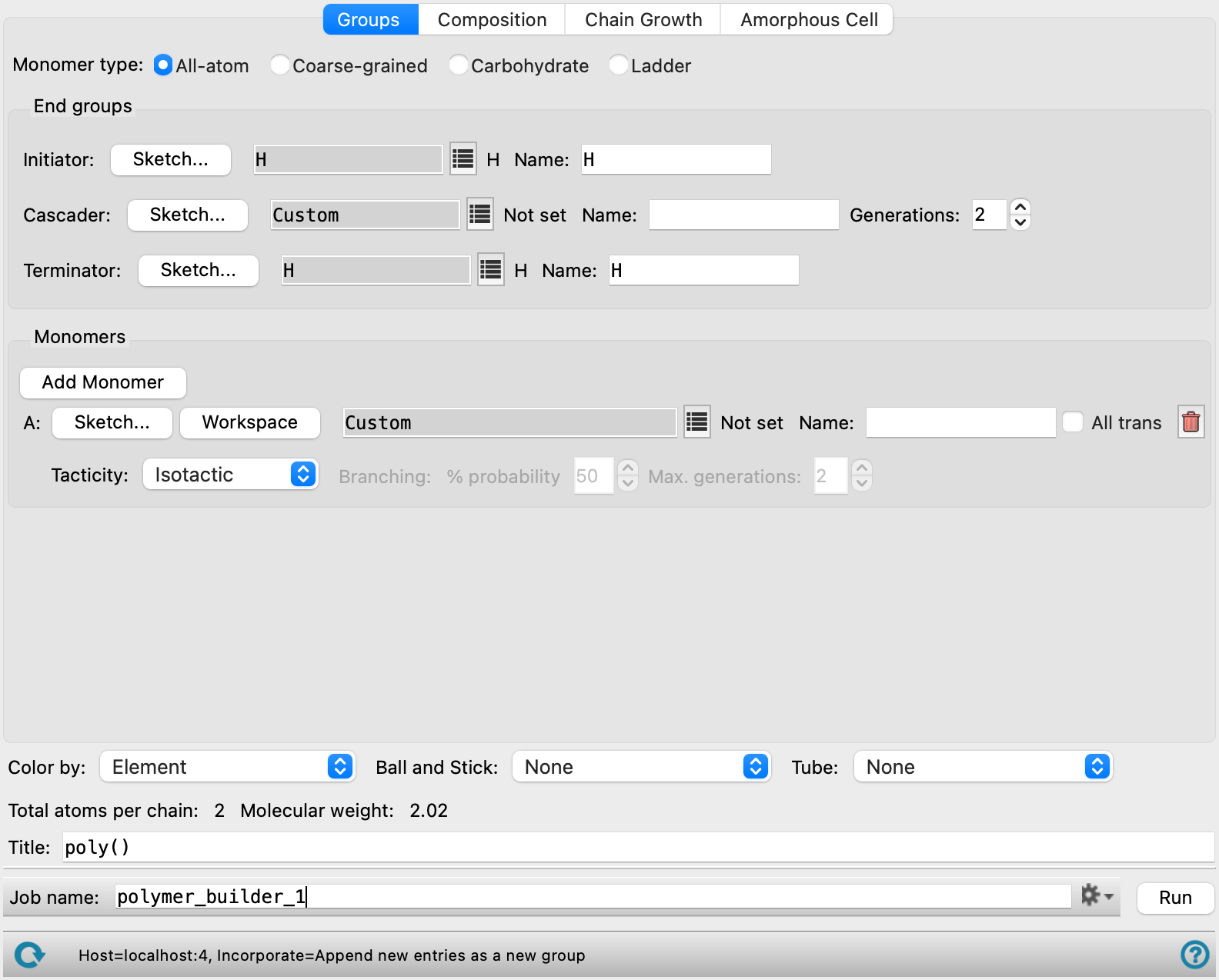
Groups tab
In this tab you specify the chemical groups you want to use for the polymer: initiator, cascader, terminator, and monomers. How these are arranged is specified in the Configuration tab.
There are some common controls for each type of group, which are described first. Descriptions relating to each type of group are given next. Only a few of these are available for coarse-grained monomers and for carbohydrates.
- Sketch button
-
This button opens a panel in which you can sketch the structure of the group in 2D. In addition to drawing the structure, you will also have to label groups as R groups, which you can do from the shortcut menu for the atom to be converted to an R group. The labels and their requirements are discussed with the group types, below.
Each instance of this panel has an option menu and several buttons at the top, which you can use to load or save templates, or clear the drawing area.
-
Template option menu—Choose an existing template to customize, or choose Custom to draw a new group.
-
Save New Template button—Save the current structure as a new template. Opens a dialog box in which you can name the template.
-
Manage Templates button—Manage the custom templates. You can perform the following actions:
- Delete a template. Choose a template to delete from the Template option menu and click Delete Template.
- Set the template directory. Click Change Custom Template Directory and navigate to a new location for the templates, or click Use Default Directory to return to the default directory for custom templates.
-
Import from Workspace button—Import the current Workspace structure into the panel. The structure is drawn in 2D, and you can modify and label it.
-
Clear Sketcher button—Clear the drawing area of all structures (which are discarded).
Below the drawing area there is a Cancel button, to return to the main panel without setting up a structure for the group, and a Use This Structure button, to use the drawn structure for the group and close the panel.
The menu, toolbar and drawing area are all common components that are used in multiple places. These features are described in detail in 2D Workspace Panel.
-
- group title text box
-
The title of the group is displayed in this text box. It is set to Custom by default
- group selection button
-
click this button to open a selection tool from which you can choose a template group. The tool has the following features:
-
Search text box. Type the text you want to search for in the group name. The list of groups is restricted to those containing the search text as you type.
-
Filter button. This button shows a list of check boxes for applying filters on group categories. Each selected filter category is applied to the list of groups (AND logic) from the list on this menu.
-
group list. Choose a group from the list. The list is dynamically updated when you use the search or filter tools.
-
-
The list contains the available template molecules for the group, including any templates you defined in the Sketcher panel.
- Empirical formula display
-
The empirical formula of the group is displayed to the right of the option menu.
- Name text box
-
This text box shows the name of the group. If you chose a template, the name is filled in from the template name. You can set or change the name by editing the text in the text box.
The specific features of this tab are described next.
- Monomer type options
-
Select the type of monomer to use in building the polymer.
-
All-atom—use monomers that are 3D all-atom structures. All of the features are available.
-
Coarse-grained—use monomers that are coarse-grained particles. The End groups section is not available, and in the Monomers section, the only controls available for defining the monomer are the Workspace button, the Name text box, and the All trans option.
-
Carbohydrate—use carbohydrates as monomers. In the End groups section, only the Initiator and Terminator settings are available. In the Monomers section, you can select alpha-D-glucose, beta-D-Glucosamine, beta-D-glucose, oxidized alpha-D-glucose (CH2OH replaced with COOH), or xanthan. Xanthan cannot be combined with the other monomers in the list.
-
Ladder—use monomers that have two connection points on each end for polymerization into a ladder polymer. In the End groups section, only the Initiator and Terminator settings are available. In the Monomers section, you can select 9,10-dihydro-9,10-dimethyl-9,10-ethanoanthracene-2,3,6,7-tetrol, 5,5',6,6'-tetrahydroxy-3,3,3',3'-tetramethyl-1,1'-spirobisindane, butadiene, or tetrafluoroterephthalonitrile. The Chain growth tab is not available when you select this option, as the growth settings are predetermined.
Ladder polymers are useful for membranes and batteries.
-
- End groups section
-
This section specifies the groups that are used to initiate or terminate polymerization, or to create a cascade. Each of the three types of end group have common features, which are described above. The specific conditions on each type are described here; in particular the labels that must be applied to define the points at which the bonds are formed.
- Initiator settings
-
These controls define the initiator for the polymerization. The initiator must have at least one R group defined, which is the group that is discarded when forming a bond with the monomer. If you create your own initiator, you must add an R1 label to the group that is discarded.
For example, if your initiator is a Cl atom, build an ethane molecule, change one carbon to Cl (hover over the atom and type Cl), and change the other to R1 (right-click and choose Set R Group → R1). The molecule you end up with should be represented as Cl–R1.
You can add multiple R1 labels, and the (same) polymer is built from each point on the initiator that is so labeled. This enables you to build dendrimers. You do not have to use an initiator with multiple R1 groups to start building a dendrimer, but you can do so if you wish.
- Cascader settings
-
These controls define a cascader, which is used to create dendritic structures. The cascader must be labeled with one R1 group and two or more R2 groups. The R2 groups define points at which the chain from the initiator is replicated, to form a dendritic structure.
In addition to the controls to define the group, there is a Generations box, in which you can define the number of replications of the polymer chain in the dendrimer. The minimum number is 2, which means that there is one cascader on each chain from the initiator, to which copies of this chain are attached in place of the R2 groups.
- Terminator settings
-
These controls define the terminator of the polymerization. A terminator group must have exactly one R1 group defined (and no others).
- Monomers section
-
In this section the monomer units for the polymerization are defined. For carbohydrates, only the Add Monomer button, the monomer option menu, the Name text box, and the Delete button are present.
- Add Monomer button
-
Click this button to add a monomer unit. A new set of controls for a monomer unit is added below the last set of monomer controls. The monomers are labeled with letters, A, B, C, and so on. These letter codes are used in the Composition tab to specify the order in which the monomer units are used.
- Monomer group definition controls
-
These controls define the monomer structure. You must define the monomer as it is in the polymer, not in the isolated molecule.
-
Sketch button—sketch the monomer in the 2D sketcher. This button is not present for coarse-grained monomers or carbohydrates.
The monomer group must have a single R1 group for the head, and a single R2 group for the tail. For example, for polyethylene, the monomer must have a single C–C bond, with two hydrogens and one R group at each end. To create this monomer, you would draw butane, and convert the terminal carbons to an R1 and an R2.
If you want to create branched polymers, you can add an R3 group to the monomer to designate a point where a new chain can be attached.
Ladder monomers must mark the two head atoms as R1 and R3, while the two tail atoms must be R2 and R4.
-
Workspace button—use the Workspace structure for the monomer. When you click this button, the Mark Monomer Head and Tail Panel opens, with Apply to set to Workspace. You should then pick the head and tail atoms, which must have at least one hydrogen attached to them for the capping atom, or pick the capping atoms, which must be terminal atoms, not necessarily hydrogen. These capping atoms are replaced when the polymer is built (i.e. assigned as R1 or R2). The title of the Workspace structure is used for the Name by default. Not present for carbohydrates.
-
Monomer title text box—This text box shows the monomer that was selected. It is set to Custom by default, or if you click the Sketch button or the Workspace button.
-
monomer title text box—displays the title of the monomer. It is set to Custom by default
-
monomer selection button—click this button to open a selection tool from which you can choose a monomer. The tool has the following features:
-
Search text box. Type the text you want to search for in the monomer name. The list of monomers is restricted to those containing the search text as you type.
-
Filter button. This button shows a list of check boxes for applying filters on monomer categories. Each selected filter category is applied to the list of monomers (AND logic) from the list on this menu.
-
monomer list. Choose a monomer from the list. The list is dynamically updated when you use the search or filter tools.
-
-
Name text box—enter a name for the monomer. This text box is filled in automatically from the title of the Workspace structure or the name of the standard monomer, if you use either of those as the source of the monomer.
-
- All trans option
-
Select this option to ensure that the internal configuration of the monomer unit is all trans. If you deselect this option, the geometry is determined by the minimization of the monomer unit when it is converted from 2D to 3D. This includes the dihedrals involving the first atom (or particle) on the next and previous unit (or, alternatively, the dihedrals involving the R1 and R2 groups in the monomer). Not present for carbohydrates.
- Tacticity option menu
-
If the monomer unit is chiral, you can specify the tacticity of the polymer, by choosing an option from this option menu: Isotactic (same stereochemistry), Syndiotactic (alternating stereochemistry) or Atactic (random stereochemistry). Not present for carbohydrates.
- Branching controls
-
A monomer group can have an R3 group as well as an R1 and an R2 group. The R3 group designates a point where a new chain can be attached, to create branched polymers. If a monomer group has an R3 group, the Branching controls are enabled, and you can specify the probability of branching and the maximum number of generations when branching.
The branching probability is applied to each monomer unit independently, to decide whether it will branch or not. With this approach, there is a small but finite probability of none of the monomers branching, or of all of them branching.
Each branch is created by taking a copy of the chain before branching and attaching it to the branch point. If you specify more than two generations, branch points are chosen at random for each added chain, so the branch points can be different in each chain that is added in each generation. The process is repeated for each subsequent generation.
If an R3 group is not chosen as a branch point in the random selection, it is replaced with the terminating group.
-
These controls are not present for carbohydrates.
- Delete button
-
To delete a monomer, click the delete (X) button on the right. The controls for the monomer are removed from the panel and the information on the monomer is discarded.
Composition tab
In this section you specify how the monomers are arranged to form the polymer, and the number of repeat units in the polymer. The type of polymer that can be formed depends on the number of monomer units, and is reflected in the options of this section. These three options, with their controls, are described below.
The monomer names, the polymer composition (e.g. A2B6) and the polymer sequence (e.g. ABBBAB) are returned as Maestro properties, if you build a single chain (but not for amorphous cells).
- Homopolymer option
-
If there is only one monomer specified, this is the only option available and it is selected by default.
- Number of monomers text box
-
Specify the length of the polymer chain. The polymer can be branched if you specified a branch point on the monomer. In this case each of the branches has the number of monomers specified in this text box.
- Degree of polymerization text box
-
Specify the degree of polymerization for the Flory-Schulz distribution of polymer lengths. The degree of polymerization is the average length (in monomer units) of the polymer chains in the distribution. This text box is shown in place of the Number of monomers text box if the Flory-Schulz distribution option is selected.
- Flory-Schulz distribution option
-
Use a Flory-Schulz distribution of polymer lengths instead of a fixed length. See Molecular Weight Distribution In Linear Step-Growth Polymers for more information on this distribution. This feature is only available when creating an amorphous polymer cell. If you choose this option, the polydispersivity index is written to the log file
jobname-driver.log. The distribution of chain lengths is written to a filejobname-distribution.csv. A different distribution is given for every new random seed.
- Block or periodic copolymer option
-
If you specified more than one monomer, you can construct a block or periodic copolymer by choosing this option. You can then specify the repeat unit and the number of repeat units.
- Repeat unit text box
-
Specify the repeat unit in this text box, using the letter codes for the monomer units as displayed in the Groups tab. These letter codes with the monomer names are shown to the left of the Block or periodic copolymer option. To specify the repeat unit, enter the sequence of letter codes. If there are repeated monomer units, you can instead use a repeat count following the letter code, e.g. A3 is the same as AAA.
If you want to enumerate several polymers in which one or more positions has each of the monomers, you can use a * to designate an enumeration site. A list of repeat units is constructed that contains each of the possible monomers at this site. For example, if you have three monomer units, then AB* generates the three repeat units ABA, ABB, and ABC. Each of these is used in a separate polymer: ABAABAABA..., ABBABBABB..., and ABCABCABC...; only one repeat unit is used in each polymer. You can have more than one enumeration site. For example, with two monomers, A*B* would generate four repeat units, AABA, AABB, ABBA, and ABBB. The number of polymers generated is shown to the right of the number of repeat units as Enumerated polymers.
- Number of repeat units box
-
Specify the number of repeat units (as defined above) in a polymer chain. If the polymer is branched or dendritic, each chain that is initiated from a branch point or cascader has this length.
- Random copolymer option
-
If you specified more than one monomer, you can construct a random copolymer by choosing this option. This option is not available for carbohydrates.
- Monomer concentration boxes
-
Specify the relative concentration of each monomer in these boxes, which are labeled with the letter code for the monomer. The letter codes with the monomer names are shown to the right of the Random copolymer option. The approximate composition is given to the right of the Number of monomers box. The concentration values are used throughout the polymer building process.
- Propagation definition preference options
-
Select this option to provide propagation data, and choose the data type, from Coupling probability or Reactivity ratio. Nonstandard couplings are disabled when you select this option, so the coupling is always tail-head.
- Propagation data table
-
Specify values for the coupling probability or the reactivity ratio. Each row or column corresponds to a particular monomer. The rows correspond to the monomer at the end of the chain, the columns to the incoming monomer. If you chose Reactivity ratio, the diagonal values cannot be set, as they are by definition 1.
- Import from CSV button
-
Load a CSV file containing coupling probabilities or reactivity ratios for the monomers. In the CSV file each row or column should correspond to a particular monomer. The rows correspond to the monomer at the end of the chain, the columns to the incoming monomer. If you chose Reactivity ratio, the diagonal values cannot be set, as they are by definition 1.
Click to open the Import Coupling Probability CSV dialog box, where you can navigate to the file. The name of the file you selected is displayed to the right of the Load button. The values will be imported to the propagation data table.
- Number of monomers box
-
Specify the number of monomers in the copolymer chain. If the polymer is branched or dendritic, each chain that is initiated from a branch point or cascader has this length.
- Steady state composition text
-
This text shows the expected composition of the final polymer as determined by the number of monomers and the monomer concentrations. In the random process, there may be polymer chains whose composition deviates from this formula, but the average composition should be very close. The composition can be enforced on all chains with the Enforce option.
- Enforce option
-
Enforce the steady state composition by eliminating polymer chains that do not exactly match the displayed composition.
Chain growth tab
In this tab you can set various parameters for the growth of the polymer chain. This tab is not present for ladder polymers.
- Nonstandard coupling probabilities boxes
-
If you want to allow tail-to-tail or head-to-head couplings, instead of just head-to-tail couplings, you can set the percentage probabilities of each type occurring on the addition of another monomer, in the Tail-tail and Head-head boxes. The random number generator is used in conjunction with these percentage probabilities to determine whether the coupling of the next monomer unit is nonstandard, when building the polymer. To introduce multiple nonstandard couplings, you must set probabilities for both types.
Not available for carbohydrates.
- Backbone dihedral options and boxes
-
You can set backbone dihedral angles or specify a range of angles with these options and boxes, and choose which classes of backbone dihedrals to set. Not available for carbohydrates.
- Set option and box
-
Select this option to set backbone dihedrals to a specific angle in degrees, which you enter in the box.
- Random option and boxes
-
Select this option to allow random selection of backbone dihedrals within a specified range of angles. You can set the limits of the range in the Min and Max boxes. Select Avoid clashes to retry dihedrals if there is a clash (the nonbonded interatomic distance is less than the scaled sum of the atomic van der Waals radii). You can set the number of retries and the scaling factor by clicking Options and making changes in the dialog box that opens.
- Avoid clashes option and Options button
-
Select this option to avoid clashes when randomly selecting backbone dihedrals. Clashes are considered to occur if the nonbonded interatomic distance between two atoms or particles is smaller than the scaled sum of the atomic van der Waals radii of the atoms. If a clash is detected, all of the dihedrals between the clashing atoms or particles are retried until a non-clashing orientation is found, or the number of tries exceeds a specified maximum. You can set the van der Waals scale factor and the maximum retries in the Backbone Dihedral Clash Options dialog box, which you open by clicking Options.
- Affected dihedrals options
-
Select one of these options to specify which dihedrals are being set. If you selected the Random option, a different value is assigned to each dihedral.
- Coupling bond—Set the value for the dihedral between the monomer units.
- Intermonomer—Set the value for the coupling bond dihedral and the two dihedrals around the bonds next to the coupling bond.
- All—Set the value for all backbone dihedrals. This option is overridden if you select All trans in the Groups tab.
- Coupling angle options
-
Select one of these options to specify the intermonomer coupling angle for coarse-grained systems. The coupling angle is defined using three atoms, H1, T1, H2, where H1 is the head atom for monomer 1, T1 is the tail atom for monomer 1, and H2 is the head atom for monomer 2. The options for specifying the coupling angles are:
-
Set—Specify the value of the intermonomer coupling angle to use for all angles.
-
Random—Specify a random value for each intermonomer coupling angle given the Min and Max values specified.
-
Current—Use the current angle from the input monomer for all intermonomer coupling angles.
-
- Set random number seed option and text box
-
Select this option to specify a random seed for all random processes used in building the polymer. Specifying the seed allows you to reproduce the results, unless other factors affect them. If this option is not selected, a seed is chosen at random.
- Record bond direction information option
-
Select this option to have outputs of the builder retain bond direction information.
Amorphous Cell tab
In this tab you can create one or more amorphous cells from each of the polymers that you build. The cell is cubic, and the size is determined from the number of polymer molecules and the final density. The periodic boundary condition properties are added to the structure when the cell is created. If you requested enumeration of polymers in the Composition tab, a cell is created for each polymer. The Amorphous Cell tab is not available for carbohydrates.
The cell is built by randomly orienting and placing polymers one by one, and checking for clashes. If a clash is found, the latest polymer to be placed is placed again at random, and this process is repeated until a non-clashing placement is found or the number of tries is exceeded. If a non-clashing placement isn't found, building of the cell is tried again from the beginning. If the cell can't be built from the beginning after a specified number of trials, the density or the scaling factor for clash detection is decreased, and the process starts again.
- Create amorphous cell option
-
Select this option to create one or more amorphous cells for each polymer. The remaining options in the tab are activated when you select this option.
- Entangled chain growth option
-
Use the self-avoiding random walk algorithm to build a set of tangled polymers in the cell. In this algorithm, the initiators are placed at random and the chains grown simultaneously, adjusting dihedral angles and regrowing part or all of a chain if necessary to avoid clashes. The rebuilding is done by fragmenting at each rotatable bond, and adding it back in with random selection of the dihedral from a probability distribution.
If this option is not selected, the polymers are built first, then placed in the cell.
- Dihedral angle distribution options
-
Select an option for the probability distribution for sampling dihedral angles in the specified range:
-
Uniform—sample dihedral angles using a uniform probability distribution. This is the only option available (and is fixed) for coarse-grained polymers.
-
Boltzmann at T K—sample dihedral angles using probabilities derived from a Boltzmann distribution of the dihedral angles at the specified temperature. The potential energy surface used for the Boltzmann distribution is calculated using the force field specified below. A truncated version of the molecule being built is used for the potential energy surface, with sufficient atoms near the bond being added to provide a realistic surface. A lower temperature often yields better order along the chain and more extended molecules.
-
- Number of polymers text box
-
Specify the number of polymer molecules to place in the cell.
- Number of amorphous cells text box
-
Specify the number of amorphous cells to create. Each cell is created with a different random seed, which is taken from the settings in the Chain Growth tab. If a specific seed was specified there, the seed is multiplied by the cell number (1, 2, 3, ...) to ensure that it is different for each cell. Otherwise, a different random seed is used for each cell.
- Initial density text box
-
Specify the initial density of the polymer in g cm−3. The density may be adjusted to avoid clashes, depending on the option for the value to keep constant.
- Initial clash VDW scale factor text box
-
Specify the initial scaling factor for detecting clashes. A clash is considered to occur if the nonbonded interatomic distance between two atoms is smaller than the scaled sum of the atomic van der Waals radii of the atoms.
- Keep constant options
-
Choose an option for the quantity to keep constant when constructing the cell. The other quantity is adjusted during the placement of polymers to avoid clashes. Choosing Density keeps the density at its initial value and changes the scale factor for clashes to eliminate clashes. This option might result in polymers that are too close. Choosing VDW scale factor keeps the clash detection the same, and adjusts the density to eliminate clashes. This might result in a density that is lower than desired.
- Placement attempts per polymer text box
-
Specify the maximum number of attempts to be made when placing a polymer in the cell. For the placement algorithm, in each attempt the polymer is oriented at random and placed in the cell at random. If a clash is detected, the attempt is regarded as failed, and a new attempt is made. For the self-avoiding random walk algorithm, the attempt to place a polymer is considered to have failed if all monomers have been removed from the polymer in the effort to eliminate clashes and the polymer cannot be rebuilt. The new attempt places the initiator at the largest vacancy in the cell.
If the maximum number of attempts is exceeded, the cell is discarded and a new cell is built.
- Attempts per density/clash distance text box
-
Specify the maximum number of attempts at building a cell. If a non-clashing cell cannot be built in this number of attempts, the density is lowered or the van der Waals scaling factor is lowered, depending on the Keep constant option. The process continues until a non-clashing cell can be built, or the density or scale factor are very small.
- Create system for Desmond calculations option
-
Select this option to create a model system for molecular dynamics simulations with Desmond, instead of a simple amorphous cell. This option and related features is not available for coarse-grained polymers.
- Use monomer charges option
-
Select this option to calculate partial charges for each monomer in the polymer based on a truncated model that includes the monomer and other monomers that are directly attached to it, capped by hydrogens. The charges assigned to the central monomer in this model from the force field are then transferred to the polymer. When all charges are assigned, a linear shift is made to ensure that they sum to the correct total charge.
If this option is not selected, charges are assigned directly from the OPLS force field. If you are using OPLS4 and the polymer has more than 100 non-hydrogen atoms, OPLS_2005 charges are assigned, due to the cost of the OPLS4 algorithm.
- Force field option menu
-
Choose the force field for the simulations.
- Use customized version option
-
Use your customized version of the OPLS4 or OPLS5 force field, rather than the standard version in the distribution.
If the customized version is missing or invalid, the text of this option turns orange and an orange warning icon is displayed to the right, with a tooltip about the problem.
- Parameter set button
-
Select the set of custom parameters for the OPLS4 or OPLS5 force field. Opens the Set Custom Parameters Location Dialog Box.
- Immersed substrate option and button
-
Select this option to immerse a substrate in the amorphous cell. The substrate must be displayed in the Workspace, and must be of the same type as the monomers (all-atom or coarse-grained). To add it to the cell, click Import from Workspace. It is placed at the center of the cell in the orientation it has in the Workspace.
Structure display and naming options
These options allow you to set the display colors and molecular representation for the polymer, and the title of the structure.
- Color by option menu
-
Choose a color scheme for the polymer from this option menu. The choices are:
-
Element—Color each atom by element. This is the standard Element color scheme, with gray carbons, red oxygens, blue nitrogens, and so on. See the Atom Color Schemes topic for information on standard color schemes.
-
Monomer—Color each monomer type with a unique color. Initiators, cascaders, and terminators are considered separate monomer types for coloring. This is useful for identifying the sequence of monomers in a copolymer.
-
Monomer chirality—Color monomers that have R chirality in green, those that have S chirality in cyan, and those with no chirality in red (including initiators, cascaders, and terminators).
-
Backbone/side group—Color the backbone atoms green, the side groups cyan, and anything else red (initiators, cascaders, terminators, H attached to backbone).
-
Molecule—Color each polymer molecule with a unique color. This scheme is useful when creating an amorphous cell, to distinguish the polymers in the cell.
-
- Ball and stick option menu
- Tube option menu
-
These two option menus have the same items, for rendering the polymer structure in ball-and-stick representation or in tube representation. The default representation is wire (also known as "lines"). As tube representation is applied last, it will replace ball-and-stick representation if atoms chosen for tube were already chosen for ball-and-stick.
-
None—Do not render anything in the chosen representation.
-
Backbone—Render the backbone atoms in the chosen representation.
-
Side group—Render the side group atoms in the chosen representation.
-
R-chirality monomers—Render monomer units that have R chirality in the chosen representation.
-
S-chirality monomers—Render monomer units that have S chirality in the chosen representation.
-
Head—Render the head atom in each monomer in the chosen representation. This is the atom attached to the R1 group. The atom attached to R1 for initializers, terminators and cascaders are also considered head atoms.
-
Tail—Render the tail atom in each monomer in the chosen representation.
-
Head and tail—Render the head and tail atoms in the chosen representation. The bond between the monomer units will also be rendered in the chosen representation.
-
- Title text box
-
Specify the title for the polymer. A default title is built up from the IUPAC name of the polymer, as far as possible. This default scheme does not work for more complicated polymers.
Job toolbar
Manage job submission and settings. See Job Toolbar for a description of this toolbar.
The Job Settings button opens the Polymer Builder - Job Settings Dialog Box, where you can make settings for running the job.
Status bar
The status bar displays information about the current job settings and status for the panel. The settings includes the job name, task name and task settings (if any), number of subjobs (if any) and the host name and job incorporation setting. The job status can include messages about job start, job completion and incorporation.
Use the Reset button  to reset the panel to its default settings and clear any data from the panel.
The status bar also contains the Help button  , which opens the help topic for the panel in your browser. If the panel is used by one or more tutorials, hovering over the Help button displays a
  button, which you can click to display a list of tutorials (or you can right-click the Help button instead). Choosing a tutorial opens the tutorial topic.
Tutorials
- Building, Equilibrating and Analyzing Amorphous Polymers
- Building a Polymer-Polymer Interface Model
- Building a Carbohydrate Polymer
Quick Reference Sheets
Videos