Manipulate Cell Panel
Modify a simulation cell by swapping or flipping axes, aligning the axis origins, translating along axes, recombining a slab that was split, creating an interface, or straining the cell.
To open this panel: click the Tasks button and browse to Materials → Tools → Manipulate Cell.
The following licenses are required to use this panel: MS Maestro
- Features
- Additional Resources
Manipulate Cell Panel Features
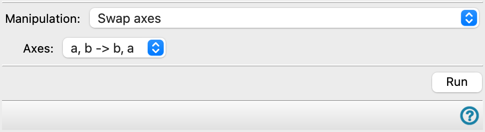
- Manipulation option menu
-
Choose the manipulation to perform on the cell. The features in the rest of the panel depend on the choice made.
Several options can operate on CMS project entries (entries that originated as CMS files). The CMS files created by the operation are stored in the project and can be exported using the Export Dialog Box. If CMS support is available for an option, it is indicated next to the option.
- Swap axes
-
Interchange a pair of lattice axes for the structure in the Workspace. The coordinates of the atoms are updated to match the new axis system. For example, swapping a and b means that the b (fractional) coordinate is copied to the a coordinate, and the a coordinate is copied to the b coordinate with a change of sign.
- Align to origin
-
Translate the structure so that the smallest fractional coordinate in the structure is zero for the choice of axis (or axes).
- Shift origin (supports CMS)
-
Shift the origin from (0,0,0) to the fractional coordinates specified in the Shift text boxes. All atoms in the structure are translated by the amount specified in the Shift text boxes. This option works on CMS entries from the project table.
- Translate to first cell
-
Translate the atoms of the structure along chosen axes, so that all the fractional coordinates with respect to these axes are within the range (0,1). Only the atoms that are outside the first cell are translated.
This is useful, for example, if you want to translate a slab in the a and b directions but not change the c coordinates. Another potential use is the generation of NEB images, where interpolation sometimes works better if atoms are initially placed outside the cell boundary; this action would move them back again.
Note: It is not required that coordinates be inside the first cell for all applications. Atom coordinates can be generated that are outside the first cell by some operations like the use of extents, building a cell when molecules cross cell boundaries (see Workspace Tools for Periodic Structures), or the addition of a slab in ESM calculations, where the origin is required to be in the middle of the slab.
- Translate to cell around origin (-0.5 to 0.5) (supports CMS)
-
Translate the atoms of the structure so that all the fractional coordinates with respect to the z-axes are within the range (-0.5, 0.5). This option works on CMS entries from the project table.
- Flip axis
-
Invert the cell along the direction of the chosen axis. The sign of the old fractional coordinates is changed, and they are shifted so that the smallest fractional coordinate is zero.
- Unwrap surface
-
If a slab that is placed perpendicular to the c axis spans the cell boundary, some actions may cause it to be split parallel to its surface, with the top piece at the bottom of the cell (in the c direction), and the bottom piece at the top of the same cell. This action moves the piece at the top of the cell down to the proper position below the piece at the bottom of the cell, so that it is not split, and it spans the boundary again. The c axis of the system must be perpendicular to the a-b plane.
- Minimum vacuum gap text box
-
Specify the minimum vacuum gap between the two surfaces of the slab, for detection of the two pieces. The top piece is detected by going from the cell boundary downwards along the c axis, checking for atoms until no atoms are detected for a distance specified by this gap. The atoms above the gap are the top piece, which is translated along the c axis to a position below the cell boundary, as described above.
- Build interface along C
-
Build a substrate-adsorbate interface with the substrate and adsorbate stacked in the C direction. The adsorbate cell is strained to match the substrate a-b plane.
- Adsorbate option menu and Importor Browse button
-
Choose the source of the adsorbate structure, and import it into the workflow for building an interface. It can be chosen as the entry included in the Workspace or imported from a file. The button text depends on the choice of the source; click the button to import from the Workspace or to browse for the file.
- Adsorbate structure lattice parameters
-
These noneditable text boxes show the lattice parameters for the imported adsorbate structure.
- Substrate option menu and Importor Browse button
-
Choose the source of the substrate structure, and import it into the workflow for building an interface. It can be chosen as the entry included in the Workspace or imported from a file. The button text depends on the choice of the source; click the button to import from the Workspace or to browse for the file.
- Substrate structure lattice parameters
-
These noneditable text boxes show the lattice parameters for the imported substrate structure.
- Strain cell (supports CMS)
-
Strain the cell by updating the lattice parameters. This can be used to creating a cell with a vacuum region, if coordinates are not updated. This option works on CMS entries from the project table.
- Structure option menu and Import button
-
Choose the source of the structure, and import it into the workflow for applying a strain. It can be chosen as the entry included in the Workspace or imported from a file. The button text depends on the choice of the source; click the button to import from the Workspace or to browse for the file.
- Structure lattice parameters
-
These noneditable text boxes show the lattice parameters for the loaded structure.
- New parameters text boxes
-
Specify the new values for the lattice parameters in these text boxes.
- Update atom coordinates option
-
Update the x, y, and z coordinates of the atoms to be consistent with the new lattice parameters. This means that the fractional coordinates are preserved, and the atom coordinates are changed.
If this option is not selected, the coordinates are preserved. The cell may have space (vacuum) between the original atoms and the cell boundary in the strain direction if the parameters are larger. If you make the parameters smaller, some atoms may be in a neighboring cell, which can cause problems in a simulation.
- Run button
-
Perform the manipulation on the cell. Any pre-existing barrier set using the Set Barrier Potential for MD Panel is removed from the structure.