Stress Strain Panel
Calculate the stress on a system as a function of the strain, from a set of molecular dynamic simulations.
To open this panel, click the Tasks button and browse to Materials → Classical Mechanics → Stress Strain → Stress Strain Calculations.
The following licenses are required to use this panel: MS Maestro, Desmond, OPLS (optional), MS Force Field Applications (optional)
- Using
- Features
- Additional Resources
Using the Stress Strain Panel
The stress-strain calculations are run as a series of molecular dynamics simulations in the NVT ensemble, with lattice parameters that are determined by an increment. The stress is calculated from the change in the pressure tensor from the initial to final (deformed) state.
The input structure must be a Desmond model system (.cms), prepared with OPLS2005, OPLS4, OPLS5, or MLFF. You can use the System Builder Panel to prepare the model system for any structure that you have. If you want to build an amorphous structure from scratch, you can use the Disordered System Builder Panel to create a model system. You can prepare a coarse-grained model system using the Coarse-Grained Force Field Assignment Panel.
You can run calculations on multiple systems simultaneously, by using multiple project entries as input. Each system is run as a separate job, and you can specify the number of processors or GPUs to use for each job in the Job Settings Dialog Box, as well as the host for the driver job and the GPU subhost.
To write out the input file and a script for running the job from the command line, click the arrow next to the Settings button  and choose Write.
Note that the calculations can only be done for elements that are covered by the OPLS force fields, which means that the system must be essentially an organic system.
The output from a stress-strain calculation can be visualized in the Stress Strain Viewer Panel (click the Tasks button and browse to Materials → Classical Mechanics → Stress Strain → Stress Strain Results). To open this panel from the entry group for the results of a job ..
..
In addition, a trajectory is created for the change in the system as a function of strain, which can be viewed in the Trajectory Player by clicking the T button for the entry containing the output structure. The results are also reported in a CSV file.
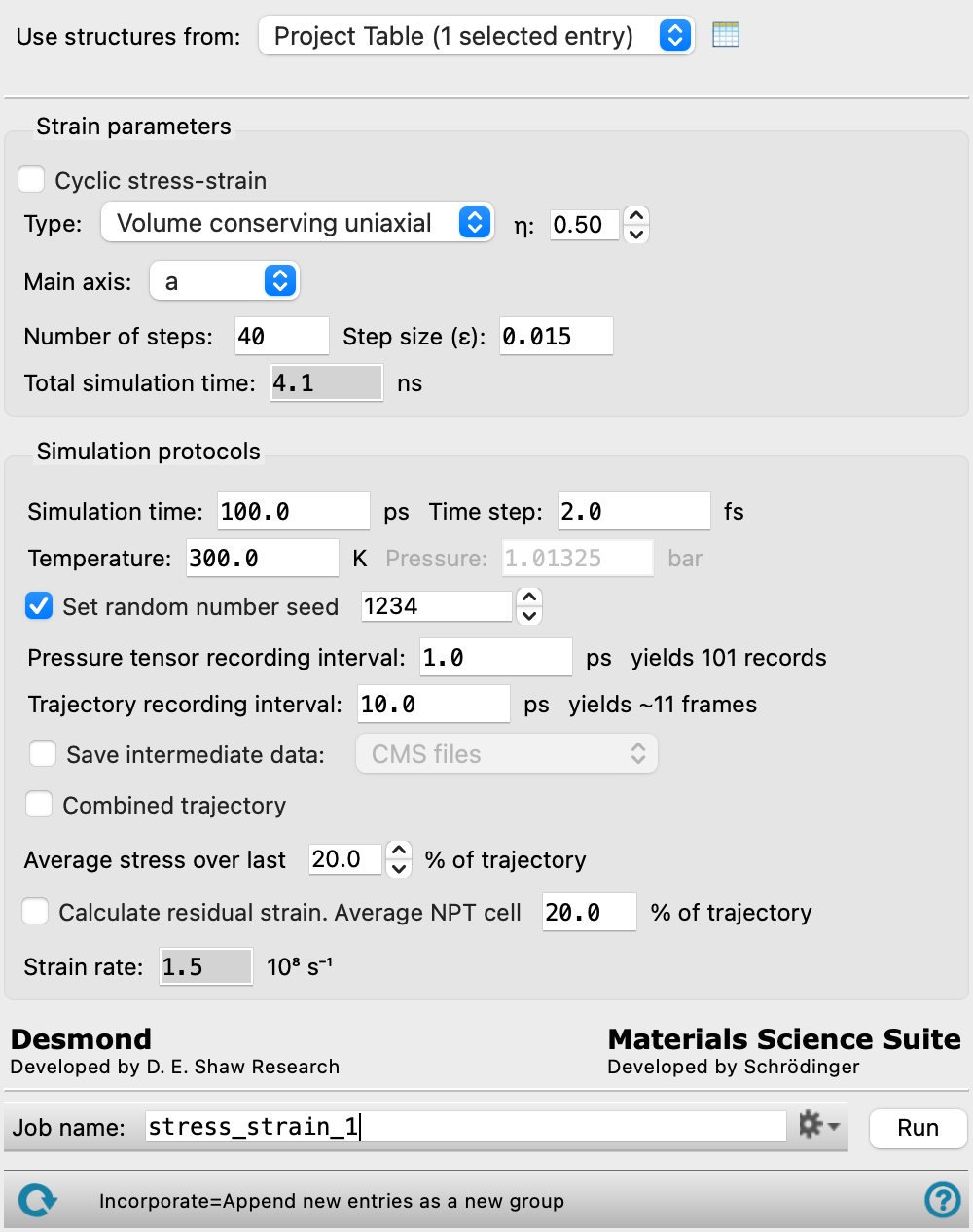
Stress Strain Panel Features
- Use structures from option menu
- Open Project Table button
- File name text box and Browse button
- Strain parameters section
- Simulation protocols section
- Simulation time text box
- Time step text box
- Trajectory recording interval text box
- Energy group recording interval text box
- Temperature text box
- Pressure text box
- Set random number seed option and text box
- Save intermediate data option and menu
- Combined trajectory option
- Average stress over last M % of trajectory option
- Calculate residual strain option
- Average NPT cell N % of trajectory text box
- Strain rate text
- Job toolbar
- Status bar
- Use structures from option menu
-
Choose the structure source for the stress-strain calculation. The structures must be properly prepared Desmond model systems.
- Project Table (n selected entries)—Use the entries that are currently selected in the Project Table or Entry List. The number of entries selected is shown on the menu item.
- Workspace (n included entries)—Use the entries that are currently included in the Workspace, treated as separate structures. The number of entries in the Workspace is shown on the menu item.
- File—Use the specified file. When this option is selected, the File name text box and Browse button are displayed.
- Project Table (n selected entries)—Use the entries that are currently selected in the Project Table or Entry List. The number of entries selected is shown on the menu item.
- Open Project Table button
-
Open the Project Table panel, so you can

- File name text box and Browse button
-
Enter the Desmond CMSfile name in this text box, or click Browse and navigate to the Desmond CMSfile. The name of the Desmond CMSfile you selected is displayed in the text box.
- Strain parameters section
-
Specify the parameters for the application of strain to the system.
- Cyclic stress-strain option
-
Select this option to apply strain to the system in a cyclical manner. A cycle is defined as increasingly applying strain up to a maximum strain, and then decreasing the strain until a minimum strain is reached. The maximum strain can be calculated as Maximum strain steps * Step size. The minimum strain can be calculated as the maximum strain - (Half cycle info: Number of steps* Step size). The number of MD jobs can be significant for cyclic stress-strain calculations and result in long simulation times. The total number of MD jobs for a cyclic stress-strain calculation can be estimated as Half cycle info: Number of steps*Number of cycles*2 + Maximum strain steps.
- Type option menu
-
Strain type to use. The strain type is defined in terms of a parameter η, which relates the transverse strain increment ε2 or ε3 to the main axis strain increment ε = ε1 by ε2 = ε3= −1+ (1+ε)−η. The choices are:
- Volume-conserving uniaxial (η = 0.5)
- Increased dilatation (η = 0.33)
- Pure uniaxial (η = 0.0)
- Isotropic expansion (η = −1.0)
- Constant lateral pressure (η not relevant but set to 0.33 to define step starting point)
- Custom
The Custom item allows you to specify η, in the adjacent text box.
- η text box
-
Specify the η parameter, if Custom is chosen from the Type option menu. For other choices from the Type option menu, this text box is noneditable or unavailable. The Custom option allows you to specify other types of strain than those available from the Type option menu, for which η is predefined.
- Main Axis option menu
-
Choose the crystal axes along which the strain is applied. All possible combinations of one, two or three of the three axes, a, b, and c are available. The calculations are performed for each selected axis independently, and the results combined.
- Maximum strain steps text box
-
The number of steps of increasing strain along the main axis to take when initially applying strain to the system. The maximum strain applied to the system can be calculated as Maximum strain steps * Step size.Only present if Cyclic stress-strain is selected.
- Number of cycles text box
-
After the maximum strain is initially applied to a system, the number of times to apply a decreasing amount of strain down to a minimum strain as determined by Half cycle info: Number of steps, and then apply an increasing amount of strain back up to the maximum strain. Only present if Cyclic stress-strain is selected.
- Number of steps text box
-
Number of steps of increasing strain along the main axis. If Cyclic stress-strain is selected, see Half cycle info: Number of steps instead.
- Half cycle info: Number of steps text box
-
The total number of steps per half cycle of a cyclic stress-strain calculation, where a half cycle is defined as taking the system from maximum strain to minimum strain, or from minimum strain to maximum strain. After the maximum strain is initially applied to the system, this value determines the number of steps of decreasing or increasing strain along the main axis. Only present if Cyclic stress-strain is selected.
- Step size (ε) text box
-
Size of the strain increment along the main axis. This is the fraction of the initial (relaxed) length of the box along the main axis by which the length is incremented, ie. Lk = L0(1 + kε).
- Total simulation time text box
-
The total simulation time of the calculation, in nanoseconds. Noneditable. For non-cyclic stress-strain, this value is determined as (Number of steps+1)*Simulation time. For cyclic stress-strain, this value is determined as (Number of cycles*Number of steps*2 + Maximum strain steps + 1)*Simulation time.
- Simulation protocols section
-
Specify parameters for the simulations at each strain value to obtain a stress value.
- Simulation time text box
-
Specify the desired simulation time in ps. This value is used for each strain value. See Total simulation time for the simulation time of the entire calculation.
- Time step text box
-
Specify the time step for the simulation in fs. For coarse-grained systems, you can increase the time step up to 15 fs.
- Trajectory recording interval text box
-
Set the recording interval for saving points on the trajectory, in ps. This is the amount of time between frames in the trajectory. The entered value is rounded to an integer multiple of the far time step size. The resultant number of records to be written is reported to the right.
- Energy group recording interval text box
-
Specify the recording interval for the energies, in ps. The number of records to be written in the energy file is reported to the right, and is recalculated when you change this value.
- Temperature text box
-
Simulation temperature, in kelvin.
- Pressure text box
-
Pressure used in the barostat for the lateral dimensions when running constant lateral pressure simulations, in bar. Only available for this type of simulation.
- Set random number seed option and text box
-
Select this option to specify a random seed to be used in the simulations. Specifying the seed allows you to reproduce the results, unless other factors affect them. If this option is not selected, a seed is chosen at random.
- Save intermediate data option and menu
-
Select this option to save data from the Desmond MD simulations.
- CMS files—save the CMS files from each of the Desmond simulations. These are the files that contain the structure and force field information.
- CMS and trajectory—save the CMS files and the trajectories from each of the Desmond simulations. Note that trajectory files can be large and may take up a lot of disk space.
- Combined trajectory option
-
Return a combined trajectory, which is generated by concatenating the trajectories from each run, in order of increasing magnitude of the strain.
- Average stress over last M % of trajectory option
-
Set the percentage of the trajectory over which the stress is averaged to yield the stress value for a given strain.
- Calculate residual strain option
-
Run a simulation in the NPT ensemble after the NVT simulation. This simulation is used to evaluate the residual strain. Not available if Cyclic stress-strain is selected.
- Average NPT cell N % of trajectory text box
-
Average the cell dimensions for the NPT simulation over the last N % of the trajectory, for evaluation of the residual strain. Not available for constant lateral pressure simulations. Not available if Cyclic stress-strain is selected.
- Strain rate text
-
This text reports the strain rate in inverse seconds, calculated by dividing the strain increment (Step size) by the simulation time.
- Job toolbar
-
Manage job submission and settings. See Job Toolbar for a description of this toolbar.
The Job Settings button opens the Stress Strain - Job Settings Dialog Box, where you can make settings for running the job.
- Status bar
-
The status bar displays information about the current job settings and status for the panel. The settings includes the job name, task name and task settings (if any), number of subjobs (if any) and the host name and job incorporation setting. The job status can include messages about job start, job completion and incorporation.
Use the Reset button
 to reset the panel to its default settings and clear any data from the panel.
 The status bar also contains the Help button
 , which opens the help topic for the panel in your browser. If the panel is used by one or more tutorials, hovering over the Help button displays a
  button, which you can click to display a list of tutorials (or you can right-click the Help button instead). Choosing a tutorial opens the tutorial topic.