Nudged Elastic Band Calculations Panel
Generate a minimum energy path (MEP) between two minimized structures by the nudged elastic band method.
To open this panel: click the Tasks button and browse to Materials → Quantum Mechanics → Quantum ESPRESSO → Nudged Elastic Band Calculations.
The following licenses are required to use this panel: MS Maestro, Quantum Espresso Interface
- Using
- Features
- Additional Resources
Using the Nudged Elastic Band Calculations Panel
To provide initial guess structures for points along the path, load structures from the Workspace as “images”. You need to provide at least two images. You can reorder the atoms to ensure that they match the ordering in the initial structure. Consistent ordering is a requirement of the calculation.
Nudged Elastic Band (NEB) calculations can be run in parallel, with options set in the Job Settings dialog box. In addition to setting the number of threads to use for parallelization, you can make settings directly for QE in the QE parallel options text box. In particular, setting -nimage to a value greater than 1 (the default) allows you to distribute images (individual calculations for steps along the NEB path) across threads. If you want to run more images than there are cores on a single node, you can run across multiple nodes, but you must configure the cluster queue for global scratch storage by setting the SCHRODINGER_TMPDIR environment variable—see Configuring for multi-node execution for more information.
You can monitor the convergence of jobs from the Nudged Elastic Band Monitor Panel.
You can restart a calculation by using the QE .cfg file from a previous calculation. Browse to click the Tasks button and browse to Materials → Quantum Mechanics → Quantum ESPRESSO → Nudged Elastic Band Restart, click Browse to locate the QE .cfg file, then click Run.
The NEB energies for each point are returned with the structures as Maestro properties.
To write out the input file and a script for running the job from the command line, click the arrow next to the Settings button  and choose Write.
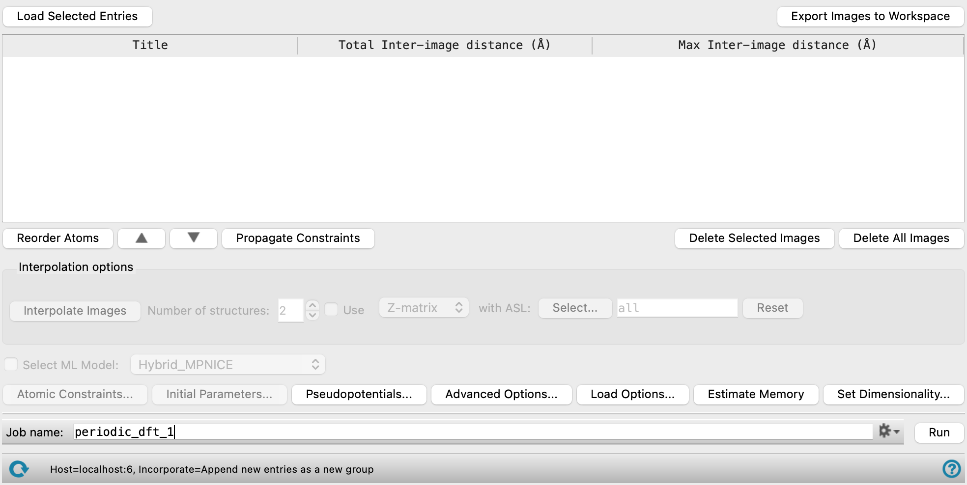
Nudged Elastic Band Calculations Panel Features
- Load Selected Entries button
- Export Images to Workspace button
- Images table
- Reorder Atoms button
- Up Arrow button
- Down Arrow button
- Propagate Constraints button
- Delete Selected Images button
- Delete all Images button
- Interpolation options section
- Atomic Constraints button
- Initial Parameters button
- Pseudopotentials button
- Advanced Options button
- Load Options button
- Estimate Memory button
- Set Dimensionality button
- Job toolbar
- Status bar
Loading of structures uses some common controls which are described first.
- Load Selected Entries button
-
Load the selected structures from the Workspace into the workflow. If you have edited an image structure in the Workspace, click this button to replace the original with the edited version.
- Export Images to Workspace button
-
Add every structure in the Images table as an entry group in the Workspace. You can use this button to display an image to inspect it and fix any problems. If you have edited the Images table, click this button to replace the entries in the entry group.
- Images table
-
Images (structures) expected to be on the reaction path are added as rows in the table. Interpolated images are added to the table. There should be enough images to adequately represent the path, and there must be at least two. The Total Inter-image distance and the Max Inter-image distance can be used to give you an idea of how much the system is moving between an image and the one before. The order of the images in the table corresponds to the path from reactant (first image) to product (last image).
- Title—The title of the entry.
- Total Inter-image distance (Å)—The sum of the displacement in every atom between the preceding image (row) and the current image, in angstroms. A value is not given for the first row in the Images table, since there is no preceding row. If a row is moved or deleted, the Total Inter-image distance is adjusted accordingly, and is always calculated from the image in the current row and the row above.
- Max Inter-image distance (Å)—The largest displacement of one atom between the preceding image (row) and the current image. A value is not given for the first row in the Images table, since there is no preceding row. If a row is moved or deleted, the Max Inter-image distance is adjusted accordingly and is always calculated from the image in the current row and the row above.
- Reorder Atoms button
-
Reorder the atoms for the selected row of the Images table, to ensure a proper mapping between the initial structure and the current structure. Only one structure can be selected at a time. The atoms of the initial structure cannot be reordered. Opens the Reorder Final Structure Atoms dialog box.
- Up Arrow button
-
Click on the up arrow (
 ) to move the selected row up in the Images table. Only one row can be selected at a time.
 - Down Arrow button
-
Click on the down arrow (
 ) to move the selected row down in the Images table. Only one row can be selected at a time.
 - Propagate Constraints button
-
Copy constrained atom coordinates from the initial image to the rest of the images.
- Delete Selected Images button
-
Remove one or more selected rows from the Images table.
- Delete all Images button
-
Clear all rows of the Images table.
- Interpolation options section
-
Specify options for the interpolation of the images.
- Interpolate Images button
-
Generate structures that are linearly interpolated between any two rows selected in the Images table. The interpolated structures are added as rows in the Images table between in the two rows used for interpolation.
By default, the structures are generated by linear interpolation for each atom along its shortest vector between initial and final structures, taking periodic boundary conditions into account. Rotation of groups of atoms may lead to unrealistic intermediate structures. Atoms that are peripheral to the reaction site may in fact migrate the opposite way across a cell to the rest of the group, because the shortest vector is chosen for each atom separately. You can also use internal coordinates for interpolation instead of Cartesian coordinates (see below), but in this case the interpolation does not take periodic boundary conditions into account.
You should always inspect the structures carefully before using them for the calculation. Click Export Images to Workspace and include the entry in the Workspace to inspect the structure. You can also edit the structure in the Workspace to fix any issues; if you do, be sure to select all the entries in the entry group before clicking Load Selected Entries to preserve all rows of the Images table.
- Number of structures text box
-
Specify the number of structures to generate by interpolation.
- Use option and menu
-
Use the chosen method for interpolation, and specify the atoms to use in the interpolation. If not selected, a linear interpolation is done using Cartesian coordinates on all atoms. These methods allow you to perform a generally more useful interpolation on the atoms whose positions are changing rapidly. The interpolation is done with these methods only for specified atoms, and ignores periodic boundary conditions. For the remaining atoms, linear interpolation in Cartesian coordinates is done.
-
Z-matrix—Use internal coordinates (Z-matrix representation) for interpolation of structures.
-
IDPP—Use the Image Dependent Pair Potential method [48] for interpolation of structures. This method uses the bond distance between the atoms involved in the transition state to create target structures for the images.
- Atom selection tools
-
Specify the atoms to use for the selected interpolation method. Click Select to open the Atom Selection Dialog Box for choosing the atoms, or enter an ASL expression in the text box. See Atom Specification Language for more information. Click Reset to clear the text box.
-
- Atomic Constraints button
-
Set or remove Cartesian constraints for atoms in the system. Opens the Atomic Constraints Dialog Box, where you can choose the constraint type (X, Y, Z, or all three), and pick atoms in the Workspace or use the Workspace selection to apply the constraints to. You can delete selected or all constraints.
- Initial Parameters button
-
Set the initial magnetization (
starting_magnetization) value and Hubbard U (Hubbard_U) and J0 (Hubbard_J0) parameters for atoms in the system. Opens the Initial Parameters dialog box, where you can pick atoms in the Workspace and set the values. The initial magnetization for a specified atom can take values between −1 (all spins down) and +1 (all spins up); the value applies to the valence electrons of the atom or ion. Alternatively, you can set the spin values, which is the difference in the number of up and down spin valence electrons (Nα−Nβ), and is proportional to the initial magnetization. The Hubbard U and J0 parameters are only used if you turn on DFT+U calculations in the Quantum ESPRESSO Calculations - Advanced Options Dialog Box. These parameters are given in eV, and can be set for a restricted range of elements, which includes the d and f block elements and C, H, O, N, As, Ga, In.You can delete selected or all settings using the Delete and Delete All buttons.
-
Optionally set the Total magnetization(
tot_magnetization) and Total charge (tot_charge) values for the system. The total magnetization is defined as (majority spin charge − minority spin charge), so 0 represents a singlet, 1 represents a doublet, 2 represents a triplet, and so on. If the value is unspecified, the magnetization is determined during the SCF cycles. If you specify the total magnetization you should not specify initial magnetizations. - Pseudopotentials button
-
Select pseudopotentials for use in the calculations. Opens the Quantum ESPRESSO Calculations - Pseudopotentials Dialog Box. The set of recommended PBE ultrasoft pseudopotentials is distributed with the suite and available from the dialog box. See Installing and Configuring Quantum ESPRESSO for instructions on downloading other pseudopotential sets.
- Advanced Options button
-
Set options for the calculation: spin treatment, density functional, dispersion corrections, Brillouin zone partitioning, occupation, SCF and optimization accuracy
- Load Options button
-
Load option settings from a Quantum ESPRESSO config file (
.cfg). Opens a file selector so you can navigate to and select the config file. The settings replace those in the Quantum ESPRESSO Calculations - Advanced Options Dialog Box. - Estimate Memory button
-
Estimate the memory needed for the selected calculations on the first input structure. After clicking the button, an Info dialog appears with the information. The estimated memory given is for a single CPU. This allows you to assess whether you have sufficient computational resources for a desired calculation without having to first run the calculation.
- Set Dimensionality button
-
Specify whether the system is a slab or bulk material. Opens the Set Dimensionality Dialog Box.
- Job toolbar
-
Manage job submission and settings. See Job Toolbar for a description of this toolbar.
The Job Settings button opens the Nudged Elastic Band Calculations - Job Settings Dialog Box, where you can make settings for running the job.
- Status bar
-
The status bar displays information about the current job settings and status for the panel. The settings includes the job name, task name and task settings (if any), number of subjobs (if any) and the host name and job incorporation setting. The job status can include messages about job start, job completion and incorporation.
Use the Reset button
 to reset the panel to its default settings and clear any data from the panel.
 The status bar also contains the Help button
 , which opens the help topic for the panel in your browser. If the panel is used by one or more tutorials, hovering over the Help button displays a
  button, which you can click to display a list of tutorials (or you can right-click the Help button instead). Choosing a tutorial opens the tutorial topic.