Solid Electrolyte Interphase Calculation Panel
Study the evolution of the solid electrolyte interphase using cycles of reaction-template based molecular dynamics simulations.
To display this panel: click the Tasks button and browse to Materials → Classical Mechanics → Solid Electrolyte Interphase Formation → Solid Electrolyte Interphase Formation Calculations
The following licenses are required to use this panel: MS Maestro, MS Reactive Interface Simulator, OPLS (optional), MS Force Field Applications (optional), Jaguar (optional)
- Using
- Features
- Additional Resources
Using the Solid Electrolyte Interphase Calculation Panel
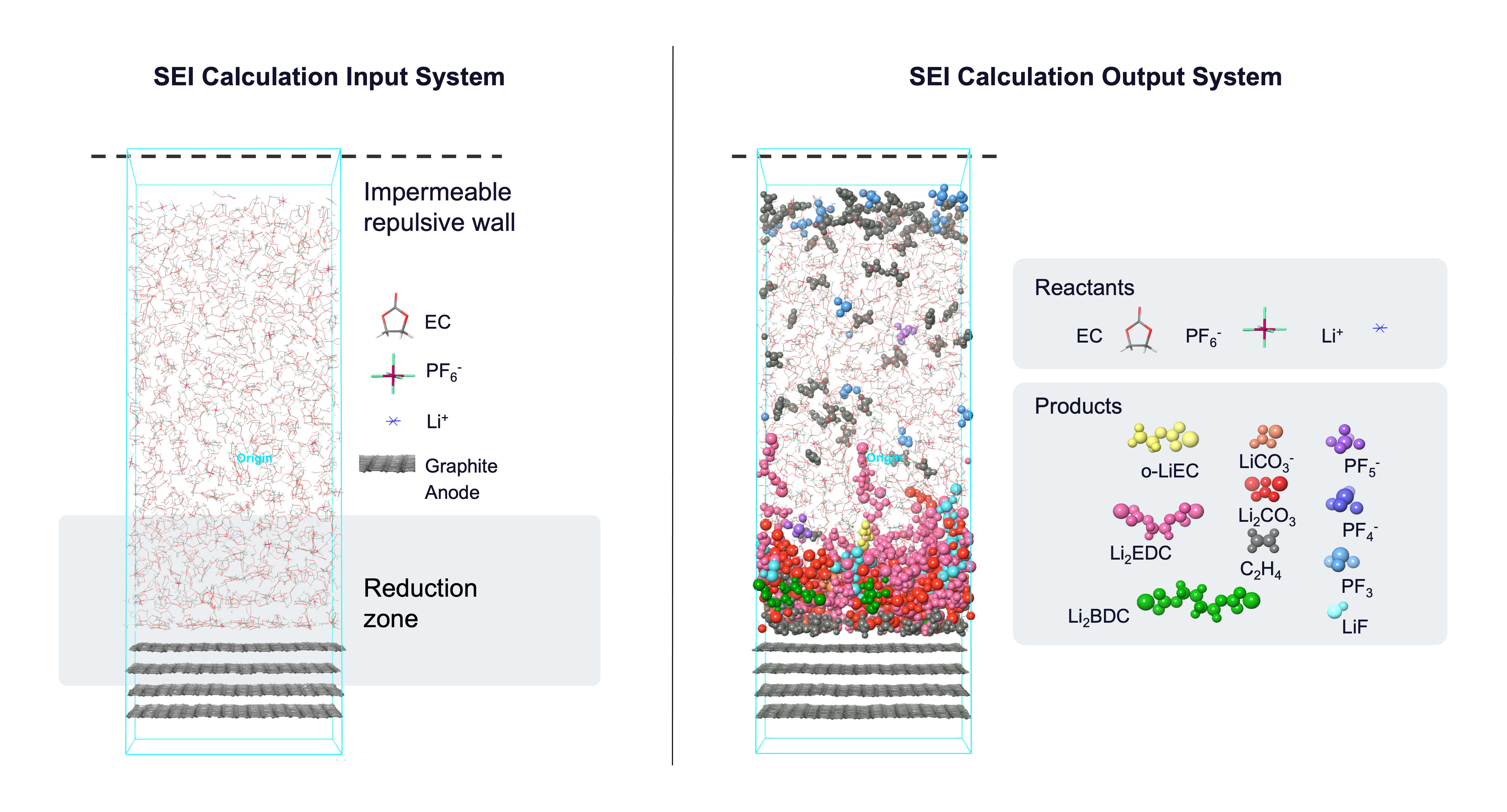
The Solid Electrolyte Interphase (SEI) panel can be used to simulate prototypical reactions occurring on the surface of the anode due to the reduction of electrolytes in a lithium-ion battery. For example, this tool can help us study the effects of temperature, salt concentration, and electrode charge on SEI morphology.
The input to the panel should be a Maestro (.maegz) or Desmond model system (.cms) consisting of an electrolyte and an electrode representative of the battery chemistry of interest. The input system should have an impermeable repulsive barrier parallel to the electrode to limit electrolyte interaction to one side of the electrode interface. See the Solid Electrolyte Interphase Calculations tutorial for guidance on building such a system.
This panel uses cycles of reaction-template based molecular dynamics (MD) to build the SEI layer at the electrode-electrolyte interphase. You can define what reactions take place in the system and set the probability and frequency of each reaction; this is called a reaction network. If reactants are found in a predefined geometric configuration (distance-criteria) at the specified time in the MD simulation, the reaction is executed based on the set probability and the MD simulation continues with the new system. For new species that form in the electrolyte, partial charges on the electrolyte atoms are calculated based on the method selected in the Method to assign atomic Charge option menu. Below is a figure showing most of the reactions supported by the panel. These reactions are useful for Li-ion battery chemistries with ethylene carbonate (EC) and lithium hexafluorophosphate (LiPF6) as electrolytes.
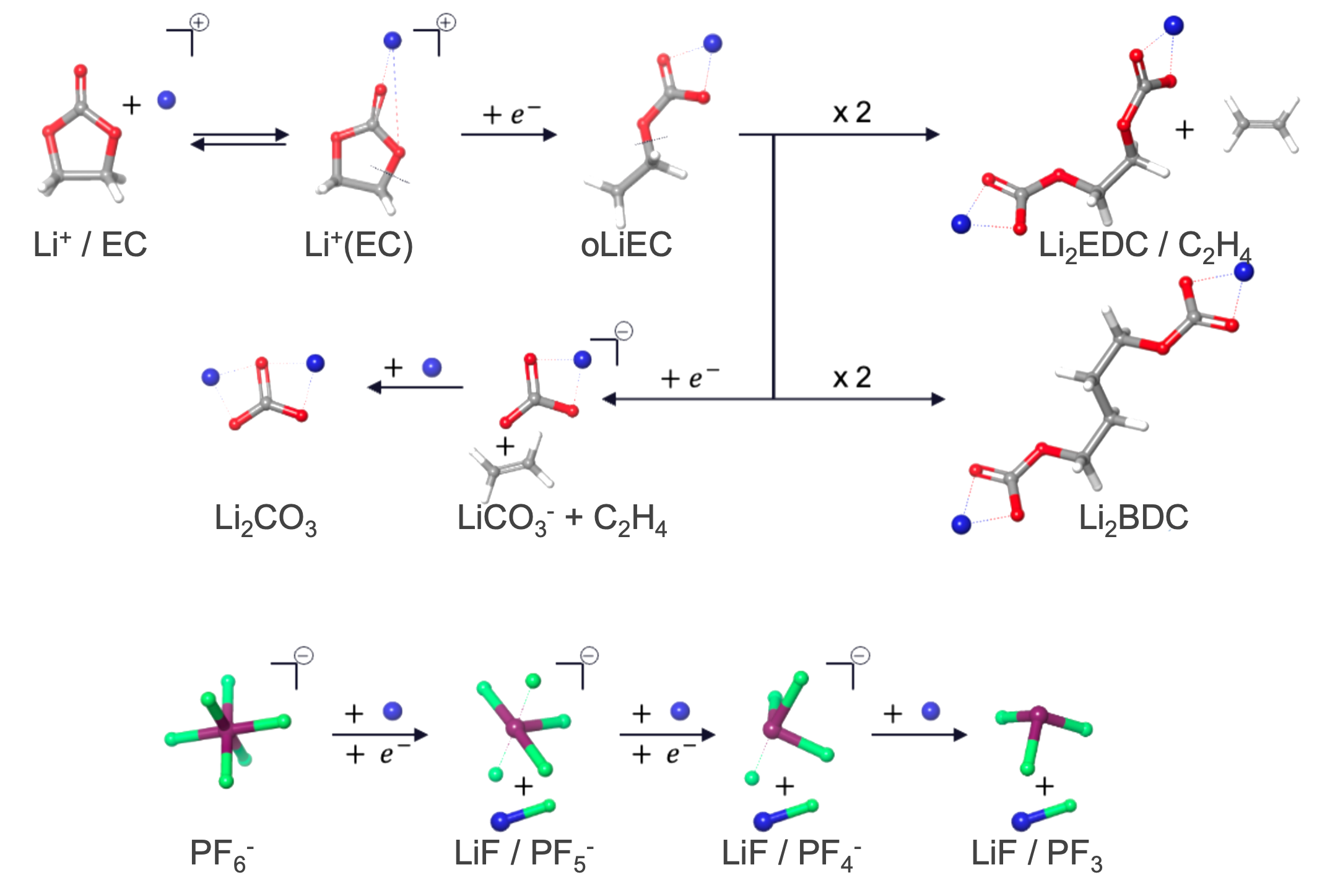
Reduction reactions in particular happen only in the user-defined region near the electrode. After every few reduction reactions, a lithium cation (Li+) is added to maintain charge neutrality in the system.
To visualize the results, you can use the Solid Electrolyte Interphase Viewer Panel (click the Tasks button and browse to Materials → Classical Mechanics → Solid Electrolyte Interphase Formation → Solid Electrolyte Interphase Formation Results). The viewer panel allows you to view the evolution of various species and their densities over the course of the simulation.
To write out the input file and a script for running the job from the command line, click the arrow next to the Settings button  and choose Write.
If you are interested in reactions beyond those provided in the panel, you can define custom reactions in the reaction configuration file (*_reaction.cfg) using the unique SMARTS of reactants and products, and run the calculation through the command line. Such reaction templates can be determined from reactivity tools such as the AutoTS: Perform Calculations Panel, Bond and Ligand Dissociation Panel, or Nanoreactor Panel. Reach out to help@schrodinger.com for assistance adding custom reactions.
Solid Electrolyte Interphase Calculation Panel Features
- Use structures from option menu
- Open Project Table button
- File name text box and Browse button
- Reactions tab
- Electrode and Electrolyte tab
- Simulation Protocol tab
- Add Relaxation option
- Ensemble class option menu
- Simulation time text box
- Time step text box
- Temperature text box
- Set random number seed option and text box
- Trajectory recording interval text box
- Save intermediate data option and menu
- Force field option menu
- Coefficient to scale custom charges text box
- Method to assign atomic Charge option menu
- Options button
- Job toolbar
- Status bar
- Use structures from option menu
-
Choose the structure source for the current task.
- Project Table (n selected entries)—Use the entries that are currently selected in the Project Table or Entry List. The number of entries selected is shown on the menu item.
- Workspace (included entry)—Use the entry that is currently included in the Workspace. Only one entry must be included in the Workspace.
- File—Use the specified file. When this option is selected, the File name text box and Browse button are displayed.
- Project Table (n selected entries)—Use the entries that are currently selected in the Project Table or Entry List. The number of entries selected is shown on the menu item.
- Open Project Table button
-
Open the Project Table panel, so you can

- File name text box and Browse button
-
Enter the file name in this text box, or click Browse and navigate to the file. The name of the file you selected is displayed in the text box.
- Reactions tab
-
- Reaction definition
-
Define one or more reactions that take place in the system during the molecular dynamics (MD) simulation. The defined reactions (reaction network) are checked at the specified frequency and are executed if reactants are found in a predefined geometric configuration.
Each defined reaction has its own set of controls: a heading row, options of templated reactions, and controls for the probability and frequency of the reaction. Addition and removal of reactions is done with the Add Reaction button at the bottom of this section and the delete buttons in the set of controls for the reaction.
- Reaction label
-
The label indicates the reaction to take place. It is updated if the reaction type is changed. The label remains visible when the reaction settings are hidden.
- reaction management buttons
-
These buttons perform display and ordering operations on the reaction. They allow for easy duplication and rearrangement of reactions.


Show or hide the contents of the reaction. When hidden, only the reaction number, label (if any) and these buttons are displayed. This is useful when you have a number of reactions and want to compare two separate reactions, for example. 
Delete the reaction. - Reaction option menu
-
Select the reaction type from the provided options. See the Using the Solid Electrolyte Interphase (SEI) Calculation Panel tab for a list of available reactions. When you select a reaction type, the label is updated with the type, and the relevant settings are displayed below these options.
- Probability text box
-
Specify the probability with which the reaction in the Reaction option menu occurs. Reactants are considered for the reaction when they satisfy the predefined distance-based criteria. If the probability is 1.0, all of the reactants which satisfy this criteria are selected and reacted. Only available when User defined is selected for the Sequence to perform reactions options.
- Frequency text box
-
Specify the frequency at which the reaction is checked, in ps. The reactions are assessed for the distance-based criteria and executed taking in account the probability.
- Add Reaction button
-
Add a reaction to the end of the defined reaction set.
- Add All Reactions button
-
Add all template reactions. This option overwrites the existing reaction network in the panel.
- Sequence to perform reactions options
-
Select the order in which the reactions are performed.
- User defined—The reactions are assessed and executed in order of the reaction definition specified, taking in account the probability and frequency set for each reaction.
- Random—The reactions are executed in a random order. The probability of all the reactions is set to 1.
- Electrode and Electrolyte tab
-
Define the electrode and the parameters for reduction reactions.
- Electrolyte section
-
Specify parameters for the electrolyte.
- Electrode section
-
Specify the electrode in the system and define additional related parameters.
- Reduction zone width text box
-
Specify the width of the reduction zone in angstroms. Reduction reactions can only occur if the reactants are present within the reduction zone. The reduction zone starts from the center of mass of the electrode and goes up to the specified distance into the electrolyte. The probability of a reduction reaction occurring in the reduction zone region decays with the distance of the reactants from the electrode.
- Electrode ASL
-
Select all atoms that are part of the electrode. This section contains a standard set of picking tools that you can use to select atoms.
- Custom charges on the electrode option
-
Set the charge on electrode atoms. If custom charges are not set, force field assigned charges are used.
- Uniform—Set a uniform charge over the whole electrode.
- Zoned—Set the interfacial and bulk electrode charges separately to define the charge on the electrode.
Custom charges on the anode atoms mimic the presence of electrons on the anode surface in a real battery system, facilitating the flow of cations towards the anode.
- Charge per atom text box
-
Specify the charge to be applied uniformly to each atom in the electrode, in atomic units. Only present if Uniform custom charge is selected.
- Interface ASL
-
Select all atoms from the electrode that are in contact with the electrolyte. This section contains a standard set of picking tools that you can use to select atoms. Only present if Zoned custom charge is selected.
- Charge per interface atom text box
-
Specify the charge to be applied uniformly to each of the interfacial electrode atoms, in atomic units. Only present if Zoned custom charge is selected.
- Charge per bulk atom text box
-
Specify the charge to be applied uniformly to each atom in the bulk electrode, in atomic units. Bulk electrode atoms do not directly interact with the electrolyte and are defined by atoms marked as electrode atoms but not interface electrode atoms. Only present if Zoned custom charge is selected.
- Simulation Protocol tab
-
Specify options for the MD simulation.
- Add Relaxation option
-
Select this option to add a series of minimizations and short molecular dynamics simulations to relax the model system before performing the reaction simulation. The materials relaxation protocol is used.
- Ensemble class option menu
-
Choose the ensemble class from this option menu. The following classes are available:
- NVT—constant particle number (N), volume (V) and temperature (T). This class represents the canonical ensemble.
-
- Simulation time text box
-
Specify the desired simulation time in ps. The simulation ends once this time has elapsed or when no reaction occurs for a time period equivalent to 100 times the minimum reaction frequency.
- Time step text box
-
Specify the time step for the simulation in fs.
- Temperature text box
-
Specify the temperature to be used, in kelvin.
- Set random number seed option and text box
-
Select this option to specify a random seed to be used in the simulations. Specifying the seed allows you to reproduce the results, unless other factors affect them. If this option is not selected, a seed is chosen at random.
- Trajectory recording interval text box
-
Set the recording interval for saving points on the trajectory, in ps. This is the amount of time between frames in the trajectory. The entered value is rounded to an integer multiple of the far time step size. The resultant number of records to be written is reported to the right.
- Save intermediate data option and menu
-
Select this option to save data from the Desmond MD simulations.
- CMS files—save the CMS files from each of the Desmond simulations. These are the files that contain the structure and force field information.
- CMS and trajectory—save the CMS files and the trajectories from each of the Desmond simulations. Note that trajectory files can be large and may take up a lot of disk space.
- Force field option menu
-
Choose the force field for the simulations.
- Use customized version option
-
Use your customized version of the OPLS4 or OPLS5 force field, rather than the standard version in the distribution.
If the customized version is missing or invalid, the text of this option turns orange and an orange warning icon is displayed to the right, with a tooltip about the problem.
- Parameter set button
-
Select the set of custom parameters for the OPLS4 or OPLS5 force field. Opens the Set Custom Parameters Location Dialog Box.
- Coefficient to scale custom charges text box
-
Scale atomic charges using the specified coefficient. This option only scales the charges on the ions. The scaling is automatically determined if custom charges are defined on Li+ atoms but can be modified using this option.
- Method to assign atomic Charge option menu
-
Select the method to use for assigning custom charges on atoms for new species that form in the electrolyte during the simulation. The choices are XTB, DFT, and User defined. If DFT is selected, you can use the Jaguar Options button to set additional parameters for the Jaguar calculation.
- Options button
-
Set Jaguar options for the atomic charge assignment. Only available if DFT is selected as the Method to assign atomic Charge. Opens the Jaguar Options - Solid Electrolyte Interphase Calculation Dialog Box. This dialog box also allows you to specify additional Jaguar keywords. The solvent (if any), level of theory, and basis set are shown to the right of the button.
- Job toolbar
-
Manage job submission and settings. See Job Toolbar for a description of this toolbar.
The Job Settings button opens the Solid Electrolyte Interphase Calculation - Job Settings Dialog Box, where you can make settings for running the job.
- Status bar
-
 to reset the panel to its default settings and clear any data from the panel.
If you can submit a job from the panel, the status bar displays information about the current job settings and status for the panel. The settings include the job name, task name and task settings (if any), number of subjobs (if any) and the host name and job incorporation setting. The job status can include messages about job start, job completion and incorporation.
The status bar also contains the Help button
 , which opens an option menu with choices to open the help topic for the panel (Documentation), launch Maestro Assistant, or if available, choose from an option menu of Tutorials. If the panel is used by one or more tutorials, hover over the Tutorials option to display a list of tutorials. Choosing a tutorial opens the tutorial topic.