Surface Tension Calculation Panel
Calculate the surface tension of single phase systems from MD simulations.
To open this panel: click the Tasks button and browse to Materials → Classical Mechanics → Surface Tension → Surface Tension Calculations.
For a tutorial, see Surface Tension.
The following licenses are required to use this panel: MS Maestro, Desmond, OPLS (optional), MS Force Field Applications (optional)
- Using
- Features
- Additional Resources
Using the Surface Tension Calculation Panel
The Surface Tension Calculation panel allows you to compute the surface tension of single phase systems, i.e., a liquid with the vacuum. The input structure must be a Desmond model system (.cms) of a liquid slab in equilibrium with the vacuum. The size of the vacuum must be at least equal to the size of the liquid, and recommended to be around twice the size of the liquid. You can use the Build Slabs and Interfaces Panel to prepare the model system. For an example workflow for building systems from scratch, please see the Surface Tension tutorial.
The input system is always rotated such that the liquid-vacuum interface, also referred to as the "fixed plane", is perpendicular to the z-direction. An MD simulation is performed in the NPNAT ensemble, where a constant normal pressure PN is applied to the fixed plane. The diagonal components of the pressure tensor at each step are used to calculate the surface tension γ:

where LZ is the length of the simulation box in the z-direction, PZZ is the component of the pressure tensor in the z-direction, PXX is the component of the pressure tensor in the x-direction, and PYY is the component of the pressure tensor in the y-direction.
The simulation should be run until the surface tension has converged. Since standard deviation for the surface tension can be quite large, the average surface tension over time may be a better indicator of convergence.
You can run calculations on multiple systems simultaneously, by using multiple project entries as input. Each system is run as a separate job, and you can specify the number of processors or GPUs to use for each job in the Job Settings Dialog Box, as well as the host for the driver job and the GPU subhost.
To visualize the results, you can use the Surface Tension Viewer Panel (Click the Tasks button and browse to Materials → Classical Mechanics → Surface Tension → Surface Tension Results).To open this panel from the entry group for the results of a job .
.
You can also use the Density Profile Panel to analyze the density profile of the results and ensure that the liquid-vacuum interface is well-defined.
The components of the surface tension equation are reported in a CSV file.
To write out the input file and a script for running the job from the command line, click the arrow next to the Settings button  and choose Write.
Surface Tension Calculation Panel Features
- Use structures from option menu
- Open Project Table button
- File name text box and Browse button
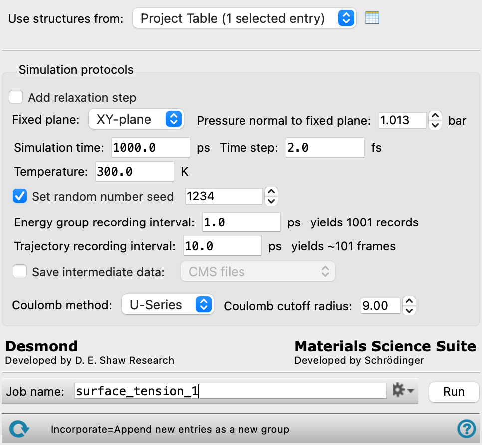
- Simulation protocols section
- Add relaxation step option
- Fixed plane option menu
- Pressure normal to fixed plane text box
- Simulation time text box
- Time step text box
- Trajectory recording interval text box
- Energy group recording interval text box
- Temperature text box
- Set random number seed option and text box
- Save intermediate data option and menu
- Coulomb method option menu
- Coulomb cutoff radius text box
- Job toolbar
- Status bar
- Use structures from option menu
-
Choose the structure source for the current task.
- Project Table (n selected entries)—Use the entries that are currently selected in the Project Table or Entry List. The number of entries selected is shown on the menu item.
- Workspace (included entries)—Use the entries that are currently included in the Workspace, treated as separate structures.
- File—Use the specified file. When this option is selected, the File name text box and Browse button are displayed.
- Project Table (n selected entries)—Use the entries that are currently selected in the Project Table or Entry List. The number of entries selected is shown on the menu item.
- Open Project Table button
-
Open the Project Table panel, so you can

- File name text box and Browse button
-
Enter the file name in this text box, or click Browse and navigate to the file. The name of the file you selected is displayed in the text box.
- Simulation protocols section
-
Specify parameters for the MD simulations from which the surface tension is calculated. Please note that the input system should already be well equilibrated.
- Add relaxation step option
-
Select this option to add a relaxation stage at the specified parameters to further equilibrate the system before beginning the simulation.
- Fixed plane option menu
-
Specify the plane parallel to the liquid-vacuum interface of the input system. In the MD simulation, the system is always rotated such that the fixed plane is parallel to the XY-plane.
- Pressure normal to fixed plane text box
-
Specify the normal pressure PN to use in the MD simulation, in bar. This is a constant pressure that is applied to the liquid-vacuum interface. By default, the value is set to be the atmospheric pressure.
- Simulation time text box
-
Specify the desired simulation time in ps.
- Time step text box
-
Specify the time step for the simulation in fs.
- Trajectory recording interval text box
-
Set the recording interval for saving points on the trajectory, in ps. This is the amount of time between frames in the trajectory. The entered value is rounded to an integer multiple of the far time step size. The resultant number of records to be written is reported to the right.
- Energy group recording interval text box
-
Set the recording interval for saving energy component information, in ps. The number of records to be written in the energy file is reported to the right, and is recalculated when you change this value.
- Temperature text box
-
Specify the temperature to be used, in kelvin.
- Set random number seed option and text box
-
Select this option to specify a random seed to be used in the simulations. Specifying the seed allows you to reproduce the results, unless other factors affect them. If this option is not selected, a seed is chosen at random.
- Save intermediate data option and menu
-
Select this option to save data from the Desmond MD simulations.
- CMS files—save the CMS files from each of the Desmond simulations. These are the files that contain the structure and force field information.
- CMS and trajectory—save the CMS files and the trajectories from each of the Desmond simulations. Note that trajectory files can be large and may take up a lot of disk space.
- Coulomb method option menu
-
Specify how long-range Coulombic interactions are handled, from U-Series or PME.
- Coulomb cutoff radius text box
-
Specify the cutoff radius beyond which interactions are treated as long-range Coulombic interactions, in angstroms.
- Job toolbar
-
Manage job submission and settings. See Job Toolbar for a description of this toolbar.
The Job Settings button opens the Surface Tension Calculation - Job Settings Dialog Box, where you can make settings for running the job.
- Status bar
-
 to reset the panel to its default settings and clear any data from the panel.
If you can submit a job from the panel, the status bar displays information about the current job settings and status for the panel. The settings include the job name, task name and task settings (if any), number of subjobs (if any) and the host name and job incorporation setting. The job status can include messages about job start, job completion and incorporation.
The status bar also contains the Help button
 , which opens an option menu with choices to open the help topic for the panel (Documentation), launch Maestro Assistant, or if available, choose from an option menu of Tutorials. If the panel is used by one or more tutorials, hover over the Tutorials option to display a list of tutorials. Choosing a tutorial opens the tutorial topic.