Workspace Configuration Toolbox
MS Maestro
stereo, dipole moment
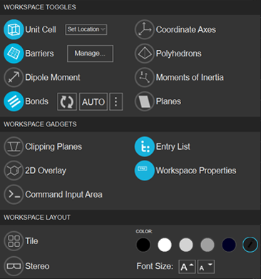
This toolbox contains options for displaying some structure-related objects, adding some tools in the Workspace, and for Workspace layout and appearance.
 To display this toolbox:
- click the More Configuration button on the Workspace Configuration Toolbar in the main window.

- Features
- Additional Resources
Workspace Configuration Toolbox Features
- Workspace Toggles section
- Unit Cell
- Display the box that marks edges of the unit cell in the Workspace.
- Set Location
- Choose the position of the displayed unit cell with respect to the coordinate system. (No changes are made to the actual coordinates of the structure with these buttons, only the displayed box.) The options are:
Fix corner at XYZ origin—fix the corner of the displayed unit cell box at the Cartesian coordinate origin.
Fix center at XYZ origin—fix the center of the displayed unit cell box at the Cartesian coordinate origin.
Keep Center at Structure Center—keep the center of the displayed unit cell box at the center of the structure. The coordinates of the structure center can be defined as ((xmax-xmin)/2, (ymax-ymin)/2, (zmax-zmin)/2), i.e. for each Cartesian coordinate, halfway between the position of the atom with the largest value of that coordinate and the position of the atom with the smallest value.
- Barriers
- Display barriers in the Workspace. Select Manage to open Set Barrier Potential for MD Panel.
- Dipole Moment
Display the dipole moment of each molecule in the Workspace as an arrow, centered on the centroid of the molecule, with a length proportional to the value of the dipole moment. If the entry has a dipole moment property (for example, from Jaguar, QM dipole X/Y/Z), this dipole moment is displayed; if it does not, the dipole moment is calculated using the coordinates and atomic partial charges (generated using the default force field). The appearance of the arrow is controlled by preferences—see Dipole moment settings.
- Bonds
- Show the connectivity of the structure, displayed as single bonds. Two atoms are considered connected if the distance between them is smaller than the sum of their covalent radii plus an offset. No account is taken of bond order in the display. Clicking the button displays or hides the connectivity. There are some buttons for controlling the bonds:

Update Bonds—update the connectivity by reapplying the distance criterion. 
Dynamic Bonds—update the connectivity after each change in the Workspace. 
Bond Options—opens a dialog box for changing the distance offset. - Coordinate Axes
Display the Cartesian coordinate axes of the structure in the Workspace. These axes rotate as you rotate the view. Note that the view axes always have x horizontal, y vertical, and z pointing out of the screen.
- Polyhedrons
Display clusters of 4-8 atomic anions around an atomic cation as polyhedrons, with the anions at the vertices of the polyhedron and the cation in the center. This representation can be useful for inorganic crystals, for example.
- Moments of Inertia
Display the principal moments of inertia of each molecule in the Workspace, as a set of orthogonal tubes whose length is proportional to the moment in the direction of the tube. The moments of inertia are calculated from the masses and coordinates of the atoms when you request their display. The actual values for each moment are displayed in the Status bar when the pointer is over the tubes.
- Planes
- Display up to 4 crystal planes, specified by their Miller indices. Opens the Crystal Planes panel, which allows you to set the Miller indices, color, and opacity for each plane. If more than one unit cell is displayed in the Workspace, you can display replicas of each plane by setting a range of displacements from the primary unit cell (Min and Max values), or move the planes parallel to the normal (Translation). You can also display arrows perpendicular to the planes.
- When the planes are displayed, you can open the Crystal Planes panel by clicking the options button:
- Workspace Gadgets section
- Clipping Planes
Display the clipping planes window, in the lower-right corner of the Workspace. This window shows a top view of the structure, with the planes that are used to clip the structure in the front and back, as well as the planes that show the clipping on the sides where the atoms are outside the screen view. See Adjusting the Clipping for more information.
- 2D Overlay
Display the 2D Overlay in the lower left of the Workspace. This pane shows the 2D structure of one of the smaller structures in the Workspace (such as ligands), with option to step through multiple structures.
- Command Input Area
Display the Commands text area at the foot of the Workspace, for entering Maestro commands. See Command Input Area and The Maestro Command Language for more information.
- Entries
Display the Entry List / Structure Hierarchy panel on the left side of the Workspace. This panel shows the list of entries in the project.
- Workspace Properties
Display entry properties of a Workspace entry as text in the upper right of the Workspace. See Displaying Entry Properties in the Workspace for more information.
- Workspace Layout section
- Tile
Display each entry in the Workspace in a separate window, or tile. When the toggle is on, tools for controlling the tiling are displayed to the right. See Tiling the Workspace for more information.
- Stereo
Display two images of the Workspace structure that can be viewed as a single stereo (3D) image with the help of a stereo viewing device.
- Color
Select the background color of the Workspace from the choices presented.
- Font Size
Increase or decrease the font size of the text in the Workspace with these buttons. See Fonts settings for more information.
This section provides toggles for displaying structure-based objects in the Workspace.
This section provides toggles for showing windows in the Workspace that provide information or access to tools for interacting with the Workspace structure.
This section provides tools for the layout and appearance of the Workspace.