Crystal Morphology Calculations Panel
Calculate surface energies of crystal surfaces for estimating relative growth rates and particle shapes.
To open this panel: click the Tasks button and browse to Materials → Classical Mechanics → Crystal Morphology → Crystal Morphology Calculations.
The following licenses are required to use this panel: MS Maestro, MS Morph, OPLS (optional), MS Force Field Applications (optional), Desmond
- Using
- Features
- Additional Resources
Using the Crystal Morphology Calculations Panel
A particle assumes the shape of that minimizes the surface energy. Thus, by calculating the surface energies of the surfaces of a crystal, one can predict its shape. The surface energy γhkl is defined as follows:

Eslab is the total non bonded energy of a slab model for the surface, Ebulk is the cohesive energy per molecule of the bulk crystal, nslab is the number of molecules in the slab model, and A is the surface area of the slab model representing the surface. The surface area of the slab model is obtained as the cross product of the in-plane unit cell vectors of the slab model. The cohesive energies and total non-bonded energies of the slab models are averaged over a trajectory from molecular dynamics simulations. The surface energies can be used to predict the particle shape via the Wulff construction method in the Wulff Viewer Panel. To open this panel from the entry group for the results of a job .
.
The molecular dynamics simulations need to be long enough for the energies of the bulk and slab models to reach a stable equilibrium. You can inspect the energies with the MS MD Trajectory Analysis Panel, using the .eaf and .cms file of each model.
To calculate the surface energies, follow these steps:
- Import an existing crystal structure into the Workspace or build a crystal structure using the New Crystal Structure Panel.
- Load the bulk crystal structure into the panel using the Load Bulk from Workspace button.
- Define the slab models for the surfaces. You can either:
- generate slab models by defining surface planes via their Miller indices and specifying the geometry of the slab; or
- load pre-built slabs. You can build slabs with the Build Slabs and Interfaces Panel or import previously built slabs with the Import Slabs Panel
- Perform molecular dynamics simulations to obtain the surface energies.
- Display the particle shape as a Wulff construct in the Wulff Viewer Panel.
To write out the input file and a script for running the job from the command line, click the arrow next to the Settings button  and choose Write.
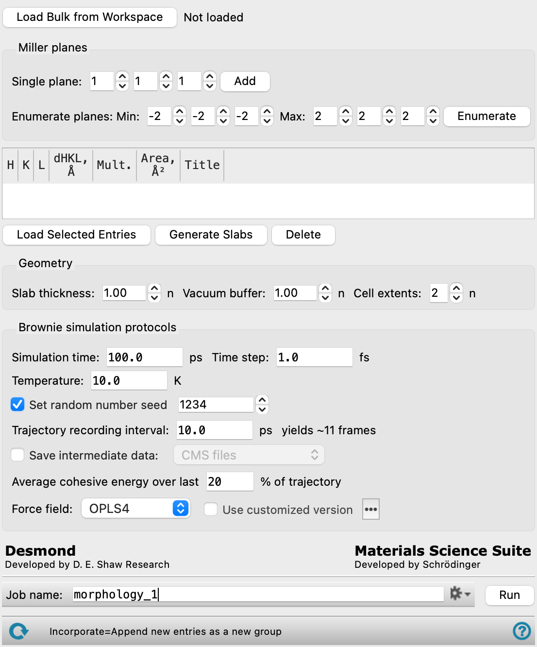
Crystal Morphology Calculations Panel Features
- Load Bulk from Workspace button
- Miller planes section
- Load Selected Entries button
- Generate Slabs button
- Delete button
- Geometry section
- Brownie simulation protocols section
- Job toolbar
- Status bar
- Load Bulk from Workspace button
-
Use the structure that is currently included in the Workspace as the bulk crystal structure.
- Miller planes section
-
Define planes for the surfaces for which the slab models are generated.
- Single plane text boxes and Add button
-
Select the Miller indices for the plane in the text boxes and click Add to add a single plane.
- Enumerate planes text boxes and Enumerate button
-
Select minimum and maximum Miller indices in the Min. and Max. text boxes and click Enumerate to generate all planes with Miller indices between the specified minimum and maximum values.
- Miller planes table
-
Lists currently defined planes with their properties, such as the h, k, and l indices, the interplanar distance dhkl, and multiplicity. If you load a pre-built slab, the area of the surface and entry title will be shown in addition.
- Load Selected Entries button
-
Select pre-built slabs in the Entry List or Project Table and click Load Selected Entries to add additional planes.
- Generate Slabs button
-
Select one or more rows in the table and click Generate Slabs to build slab models for each selected plane.
- Delete button
-
Select one or more rows in the table and click Delete to delete planes.
- Geometry section
-
Specify the geometry of the slab model. For small crystal structures, you may need to increase the size of the models in order for the molecular dynamics simulations to succeed. The minimum size is related to the nonbonded interactions cutoff parameter and should be larger than 25 Å in all dimensions.
- Slab thickness text box
-
Specify the thickness of the slab, in terms of the number of cells. The distance is taken normal to the slab bottom plane.
- Vacuum buffer text box
-
Specify the amount of empty space (measured normal to the surface) to leave above the top surface of the slab, in terms of the number of cells.
- Cell extents text box
-
Specify how often the unit cell should be repeated in the in-plane dimensions for the slab models and in all three dimensions for the bulk simulation.
- Brownie simulation protocols section
-
Change parameters for the molecular dynamics simulations.
- Simulation time text box
-
Specify the desired simulation time in ps.
- Time step text box
-
Specify the time step for the simulation in fs.
- Trajectory recording interval text box
-
Set the recording interval for saving points on the trajectory, in ps. This is the amount of time between frames in the trajectory. The entered value is rounded to an integer multiple of the far time step size. The resultant number of records to be written is reported to the right.
- Temperature text box
-
Specify the temperature to be used, in kelvin.
- Set random number seed option and text box
-
Select this option to specify a random seed to be used in the simulations. Specifying the seed allows you to reproduce the results, unless other factors affect them. If this option is not selected, a seed is chosen at random.
- Save intermediate data option and menu
-
Select this option to save data from the Desmond MD simulations.
- CMS files—save the CMS files from each of the Desmond simulations. These are the files that contain the structure and force field information.
- CMS and trajectory—save the CMS files and the trajectories from each of the Desmond simulations. Note that trajectory files can be large and may take up a lot of disk space.
- Average cohesive energy over last N% of trajectory text box
-
Specify the percentage of the trajectory that is to be used for averaging the cohesive energy. This percentage is taken from the end of the trajectory, where the results are expected to be stable.
- Force field option menu
-
Choose the force field for the current task.
- Use customized version option
-
Use your customized version of the OPLS4 or OPLS5 force field, rather than the standard version in the distribution.
If the customized version is missing or invalid, the text of this option turns orange and an orange warning icon is displayed to the right, with a tooltip about the problem.
- Parameter set button
-
Select the set of custom parameters for the OPLS4 or OPLS5 force field. Opens the Set Custom Parameters Location Dialog Box.
- Job toolbar
-
Manage job submission and settings. See Job Toolbar for a description of this toolbar.
The Job Settings button opens the Crystal Morphology Calculations - Job Settings Dialog Box, where you can make settings for running the job.
- Status bar
-
 to reset the panel to its default settings and clear any data from the panel.
If you can submit a job from the panel, the status bar displays information about the current job settings and status for the panel. The settings include the job name, task name and task settings (if any), number of subjobs (if any) and the host name and job incorporation setting. The job status can include messages about job start, job completion and incorporation.
The status bar also contains the Help button
 , which opens an option menu with choices to open the help topic for the panel (Documentation), launch Maestro Assistant, or if available, choose from an option menu of Tutorials. If the panel is used by one or more tutorials, hover over the Tutorials option to display a list of tutorials. Choosing a tutorial opens the tutorial topic.